
Sizing of gas piping networks
Program that calculates the dimensions of the pipes of a heating gas distribution network
We are pleased to provide the program designed and created by Itieffe, which calculates the dimensions (diameters) of the pipes of a gas distribution network. This tool is essential for engineers, operators and professionals in the energy sector, as it significantly contributes to the efficiency, safety and sustainability of natural gas distribution networks.
Gas distribution is a critical aspect of the global energy infrastructure and, as a result, it is essential to ensure that pipelines are sized correctly to meet ever-growing energy demand and to ensure reliable and safe distribution of gas to residential, commercial and and industrial. This program offers an advanced and efficient solution to address this crucial challenge.
Over the years, the complexities of gas distribution networks have increased significantly, requiring careful management of pipe diameters to ensure adequate pressure and uniform distribution under all operating conditions. This tool uses advanced engineering principles and up-to-date data to calculate the optimal pipe size, considering a number of key variables such as pipe type, gas type, gas flow rate and pressure drops.
Furthermore, this program can significantly contribute to environmental sustainability by helping to minimize gas leaks through efficient network design.
Overall, this absolutely free program represents a crucial step forward in optimizing gas distribution networks, improving operational efficiency, safety and sustainability. I hope this tool will prove extremely useful to everyone working in the energy sector and help promote a more sustainable and efficient future for natural gas distribution.
Sizing of gas piping networks
Program that calculates the dimensions (diameters) of the pipes of a gas distribution network
It is applied for pipes of various types (steel, copper, polyethylene)
By inserting the project data, the program carries out the elaboration by itself giving the final results sought
Instructions
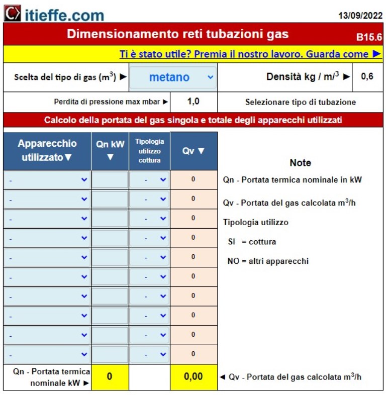
Let's start entering the data as shown in drawing 1
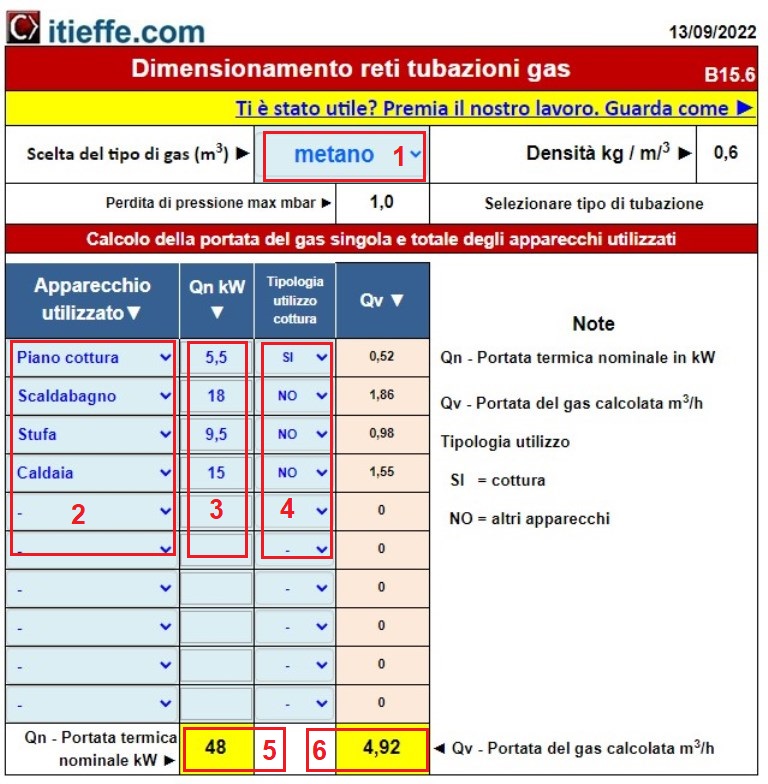
1 make the choice of the type of gas that will be used;
2 insert the device used;
3 indicate the potential of the appliance in kW;
4 describe the type of use choosing between: cooking and other appliances.
By entering the required data, you will immediately find the total nominal heat input (Qn) indicated in point 5 and the gas flow rate calculated in m3/ h (Qv) indicated in point 6.
Sizing of gas piping networks
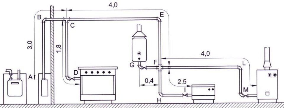
For example, let's take a system diagram for which we are going to calculate the dimensions of the pipes.
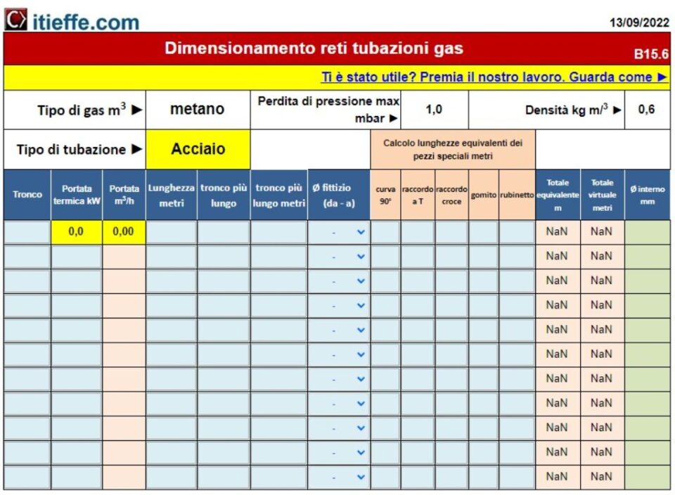
We report the data of scheme 1 in the section described in drawing 2
Let's analyze the one described in drawing 2:
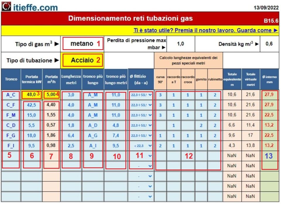
1 automatically shows the type of gas used (from the diagram in drawing 1);
2 for the type of pipe used, we choose the desired section between: steel, copper and polyethylene (in our case we will use steel);
3 value coming from the diagram shown in drawing 1;
4 value from the diagram shown in drawing 1 rounded up;
5 we rename the analyzed trunk;
6 we insert the thermal flow rates that will affect the single portions of the trunk;
7 the flow rates in m3/ h of gas, are calculated automatically;
8 we insert the length in meters of the trunk under examination;
9 we insert the name of the longest trunk that affects the two points we are analyzing;
10 we enter the length in meters of the longest trunk;
11 we enter a fictitious diameter of the intended (arbitrary) pipe. This value can be varied at the end of the calculations by choosing the one most suited to the case in question, analyzing the final diameter of the calculated pipe (The sizing proceeds section by section. If at the end of the calculation, diameters other than those used for the calculation of the virtual lengths, the sizing must be repeated with a second attempt);
12 enter the quantities of the special pieces (needed to calculate the equivalent lengths). The equivalent lengths added to the lengths of the longest logs will give us the virtual length in meters of each single log;
13 are the results sought for the internal diameter of the pipes of the entire system, required for each individual section.
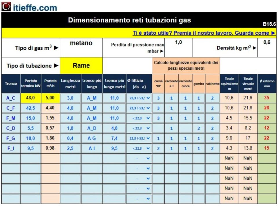
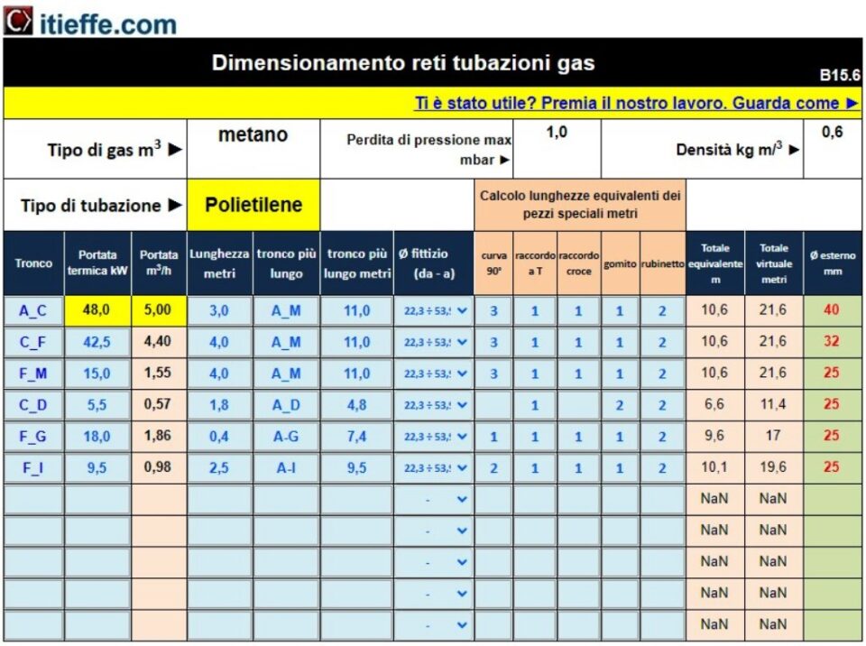
For a broader view of what is described, the same initial design values are reported, inserted in the other types of piping:
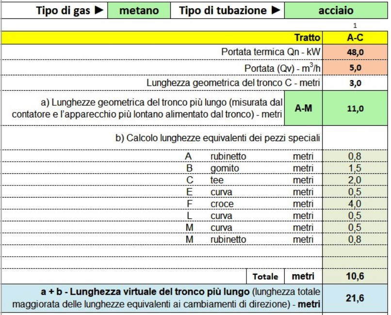
To report the data relating to the individual sections of the system, you can create and use a schematic like the one shown below:
Final indications
This is a free program that considerably simplifies the design of a gas network serving various users.
Do not take lightly what we indicate and calculate in good faith: always carry out the necessary checks first, also comparing the one shown here with your projects already carried out.
If everything matches you, then you can use this program that really speeds up (and not a little) the design of gas networks.
good job
Other free programs of the same kind offered by itieffe ▼
- Heating - Plumbing
- Pipelines
- Heating tables
- pumps
- Heating drawing diagrams
- Domestic hot water
- Combustible gases
The program below is free to use.
To access the reserved version (see below), full page and without advertising, you must be registered.
You can register now by clicking HERE