
Calculation of pressure drops in hydraulic circuits
Calculation of total pressure drops in the hot or cold water hydraulic circuit.
This program created by Itieffe, represents an important resource for hydraulic engineering professionals, water technicians, designers and anyone involved in the design and optimization of complex hydraulic systems. This tool was developed to simplify the calculation of pressure drops located within hydraulic circuits, allowing for more accurate design and optimization of system performance.
Pressure drops are a key factor in the design of hydraulic systems, influencing water distribution, pressure, flow and energy efficiency. An in-depth understanding of these losses is essential to ensure the correct functioning of systems, avoiding energy waste, excessive costs and operational problems.
Within this program, we will explore a set of tools and features designed to facilitate the calculation of localized pressure drops in complex hydraulic circuits. We will guide you through using this program, providing clear instructions and practical examples that will allow you to apply this knowledge in real situations.
The highlights of this program include the possibility of entering specific data of the hydraulic circuit, such as: type of localized resistances, diameter and speed of the water. Using this data, the program will automatically calculate the pressure drops, providing precise and detailed results for each segment of the circuit. Furthermore, the program offers the flexibility to run simulations on various scenarios, allowing you to compare different design options and find the optimal solution.
Designing efficient plumbing systems is crucial in a wide range of industries, from water supply to industrial applications and building heating/cooling. This program aims to simplify the process of calculating localized pressure drops, saving you valuable time and helping to improve the quality and efficiency of your plumbing projects.
Calculation of pressure drops in hydraulic circuits
The pressure drop of a hydraulic circuit is the resistance that it opposes to the flow of fluids inside it. The absolute total of all the head losses is called "Head of the circuit"
The prevalence is the force that the electric pump must have to overcome the pressure drops of the circuit and circulate the quantity of water required in the unit of time (depending on the selected temperature variation) inside it.
The calculation of the head is carried out considering the most disadvantaged circuit, that is the circuit that offers the greatest resistance to the motion of the fluid.
All the pressure drops in the pipes that lead from the heat generator (or chiller) to the most disadvantaged user (flow + return) are added up. Their total will be added to the total of the localized pressure drops (curves, section variations, valves, terminals, generator, etc.).
Their total is the "Prevalence of the circuit".
Breakdown of losses
Continuous pressure losses
These are the load (or pressure) losses that a fluid, moving through a duct, undergoes due to continuous resistances, due to the internal friction of the fluid itself and to the external friction due to the roughness of the duct.
The continuous head losses can be expressed both in pressure units (pascal or bar) and in fluid height (meters or millimeters of water column).
It is convenient to express their value by referring to a unit length of duct (in plumbing systems, normally: meter).
The continuous head losses can be calculated with the following general formula:
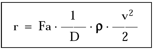
r = unit head loss (Pa / m)
Fa = friction factor (dimensionless)
D = internal diameter of the duct (m)
ρ = density of the fluid (kg / m3)
v = mean velocity of the fluid (m / s)
Localized pressure drops
These are the load (or pressure) losses that a fluid, moving through a duct, undergoes due to accidental resistances and path irregularities (reductions or widenings, curves, valves, regulators, boilers, water chillers, terminals , etc.).
Localized head losses can be determined using one of the following calculation methods:
- direct: which is based on the determination of a coefficient whose value depends on the shape of the accidental resistance;
- nominal flow rates: which refers (for each resistance) to the flow rate corresponding to a unit pressure drop (1 bar or 0,01 bar);
- equivalent lengths: which replaces any accidental resistance with an equivalent length of pipe, that is capable of giving the same pressure drop.
All our calculations will be done by the "direct method" using the following formula:
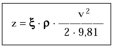
z = localized pressure drop (mm ca)
ξ = localized (dimensionless) loss coefficient
ρ = density of the fluid (kg / m3)
v = average flow velocity (m / s)
Calculation of pressure drops in hydraulic circuits
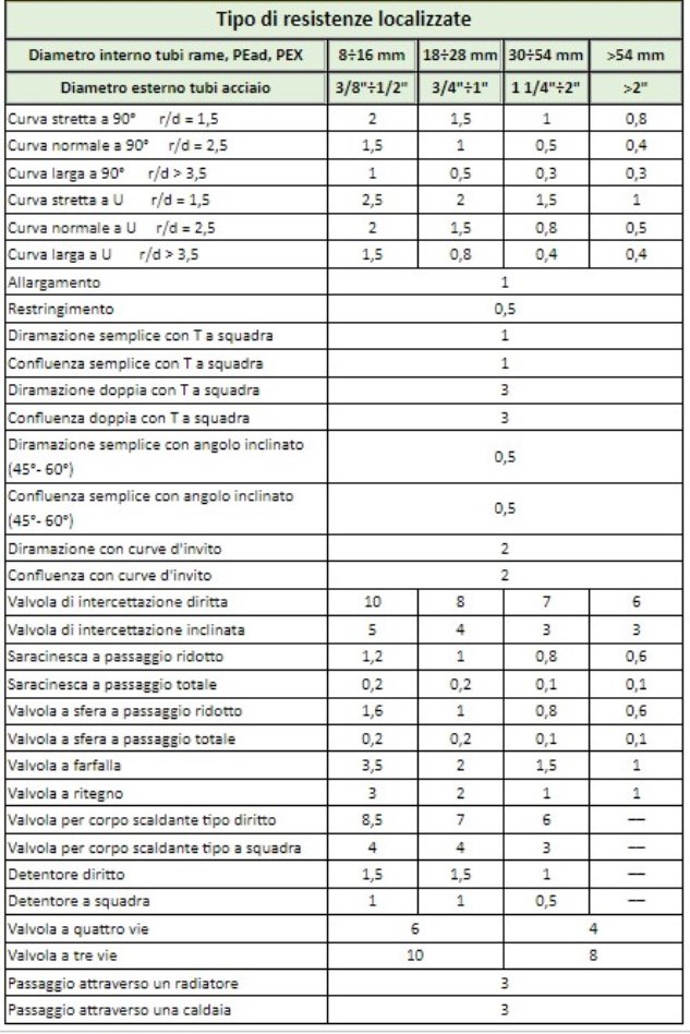
Prospectus of localized resistances
Total head losses
These are the head losses (or pressure) that a fluid, moving through a duct, undergoes due to continuous and localized resistances.
For example, in a forced circulation heating system, it is the pressures that oppose the work of the electric pumps.
The value of the total head losses is determined by adding together the continuous and localized head losses.
It should be noted, however, that the value thus obtained is not a certain value, because it is influenced by the uncertainty with which various parameters enter the calculations:
- the diameter of the pipes can vary due to production tolerances, due to the formation of encrustations or the deposit of limestone;
- viscosity is a parameter not always well known, especially when mixing with antifreeze liquids;
- roughness is a difficult factor to determine and varies significantly over time;
- the installation of the pipes can be carried out with badly welded joints (with internal burrs), or with too narrow and crushed bends;
the development of the distribution network can take place with variations during construction, due to interference with other plants or other obstacles not foreseen in the project.
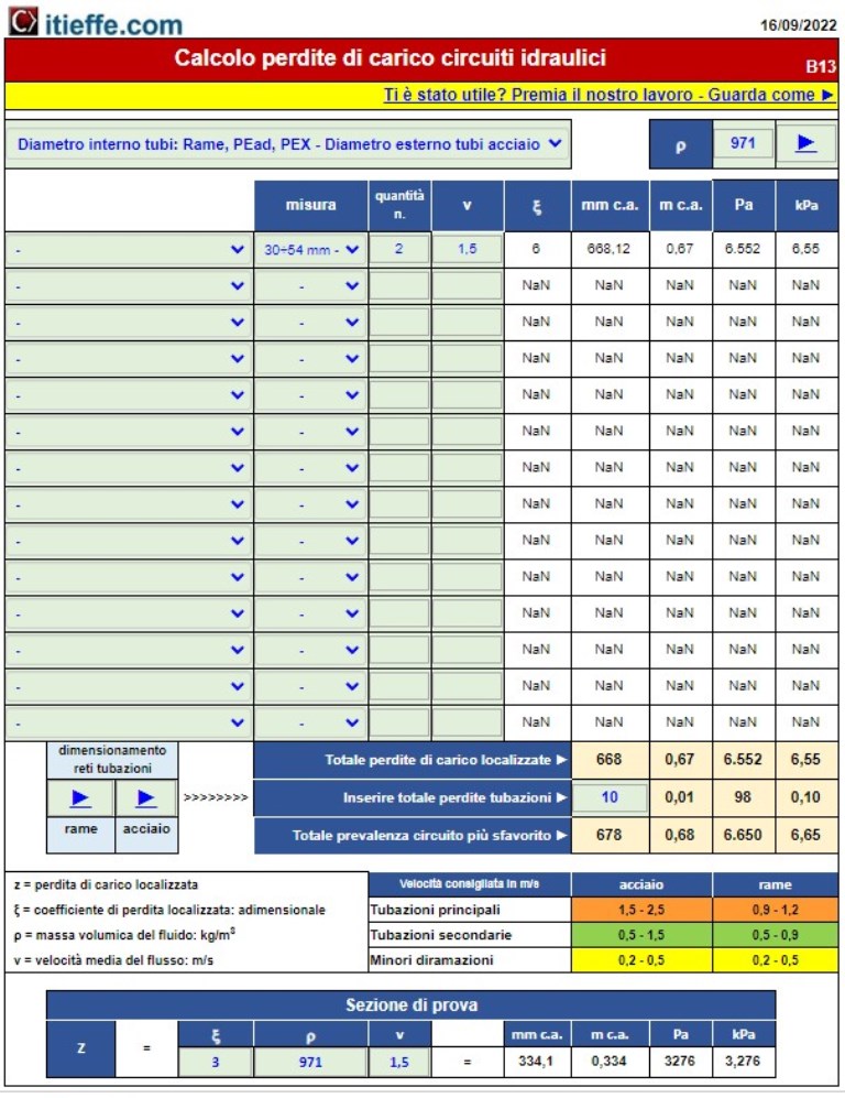
After this brief preface, we begin to analyze the program: "Calculation of pressure drops in hydraulic circuits", and how it analyzes and calculates the localized pressure drops.
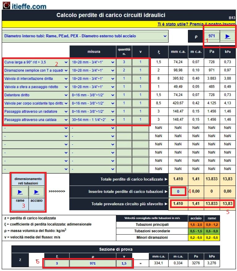
Indications highlighted in red
- ρ = density of the fluid: kg / m³. The value corresponds to a temperature of 80 ° C. Using the arrow you can connect to a program that calculates other temperatures. The result it gives is multiplied by 1.000;
- here it is possible, through a drop-down menu, to insert the resistances in play, taking care to insert those that connect points A and B of the most disadvantaged circuit;
- The arrows respectively show the links to the “Sizing of copper and steel piping networks” programs which will be discussed below;
- The value calculated with the program indicated above must be entered. Note: you can also do the opposite, that is to bring the value calculated with this program into that of the sizing of the networks;
- Prevalence result indicated in the different units of measurement;
- The test section inserted purely as an indication.
As an example, we have decided to perform the calculations on a circuit made with copper pipes (it is also possible to use others with steel pipes in millimeters and inches).
Below is indicated, as through the program "Sizing of copper piping networks", It is possible to calculate the pressure drops of the pipes involved:

Once the project values have been entered in the analyzed circuit, it is sufficient to report the value circled in red, in point 4 of the program:
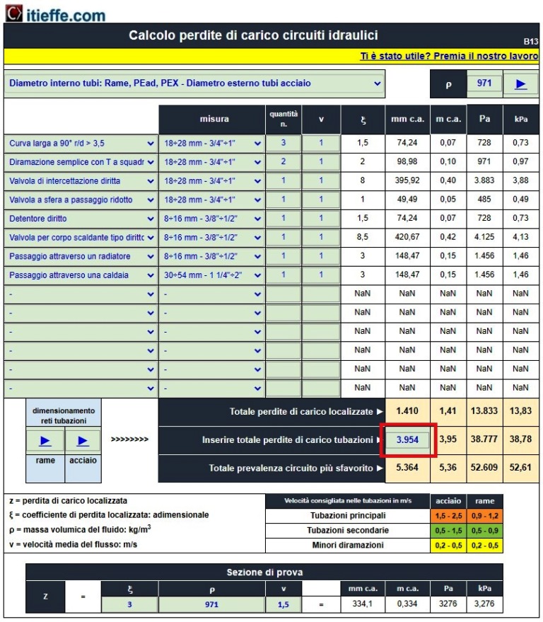
With these simple steps, we calculated the total head of the hydraulic circuit in question which, in this case, is: 5.364 mm approx.
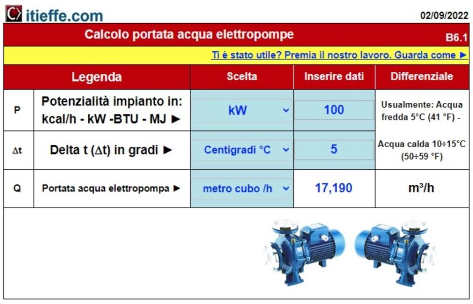
We also calculate the flow rate that the electric pump must have to circulate the water in the circuit with a temperature differential between flow and return of 10 ° C (Δt) with the program: "Sizing of electric pumps"
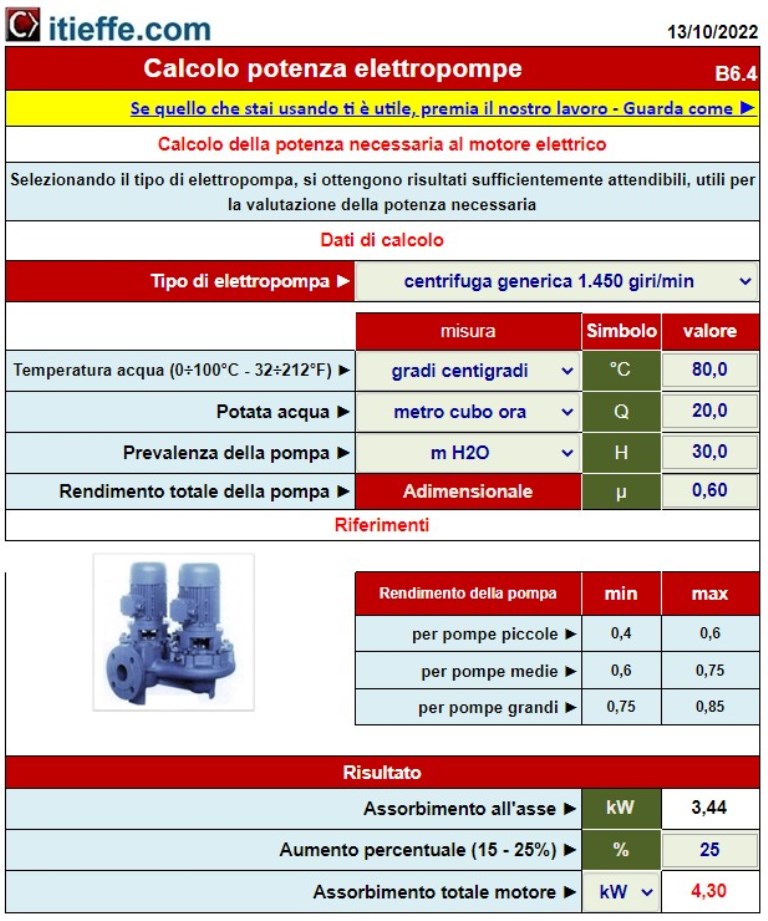
With all the available results, it is also easy to determine the electrical power required by the electric pump, which can be calculated with the following program: "Electric pumps power calculation".
Easy right?
good job
Other free programs of the same kind offered by itieffe ▼
- Heating - Plumbing
- Pipelines
- Heating tables
- pumps
- Heating drawing diagrams
- Domestic hot water
- Combustible gases
Calculation of pressure drops in hydraulic circuits
The program below is free to use.
To access the reserved version (see below), full page and without advertising, you must be registered.
You can register now by clicking HERE