
Sizing curves for air ducts
Developed to calculate the surface of the curves of quadrangular ducts, the weight and the surface of the insulation
In the field of HVAC (Heating, Ventilation, and Air Conditioning) engineering, the correct sizing of duct curves is a fundamental aspect to guarantee the efficiency, safety and effectiveness of air distribution systems. Bends are critical elements within a ducting system, and careful design is essential to avoid pressure losses, malfunctions and inefficiencies.
This program was created by Itieffe with the aim of providing operators in the HVAC industry, engineers, installers and all those interested in air distribution systems with a complete guide on the sizing of duct curves, on the calculation of their weight and on the extension of the insulation surface.
Understanding how to properly size ductwork curves is crucial to ensuring consistent airflow, minimizing energy losses and reducing operating costs. Furthermore, careful design helps to avoid unwanted noise, vibration and potentially dangerous situations within the HVAC system.
We are happy to accompany you on this journey through the world of sizing duct curves. Knowledge of these principles is fundamental to ensuring effective and efficient HVAC systems, contributing to comfort, health and sustainability in the environments in which we live and work. Accurately designing ductwork curves is an important step towards an advanced and responsible HVAC industry.
Sizing curves for air ducts
Simple program to calculate the surface of the bends of quadrangular ducts, their weight, the surface of the insulation and the form factor K
Instructions
We have already seen how to calculate the weight and surface of rectangular ducts (Calculation of the weight of the square channels surface), now let's do the same thing with the respective curves.
Let's analyze the program using in drawing:
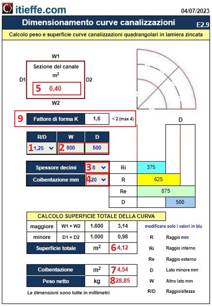
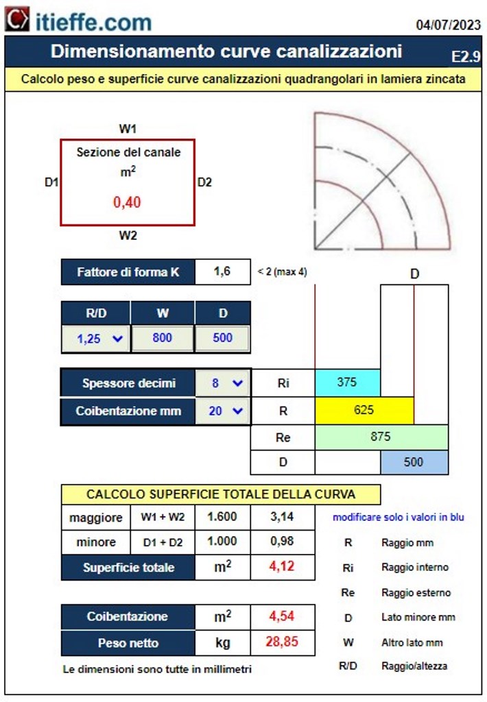
1 – using the drop-down menu, insert the ratio between Radius and Height R/D;
2 – insert the dimensions in millimeters of the longer side W = 800 mm and of the shorter side D = 500 mm;
3 – we choose the thickness of the duct in tenths of a millimetre;
4 – insert the thickness of the insulation in millimeters (if applicable).
Andiamo to analyze the results:
5 – the section of the canalization is equal to am2 0,40;
6 – with an R/D of 1,25 the total surface of the curve will be m2 4,12;
7 – if insulation is present, with a thickness of 8 tenths, it will be m2 4,54:
8 – the net weight of the bend will be 28,85 kg.
9 – form factor, in this case K = 1.6.
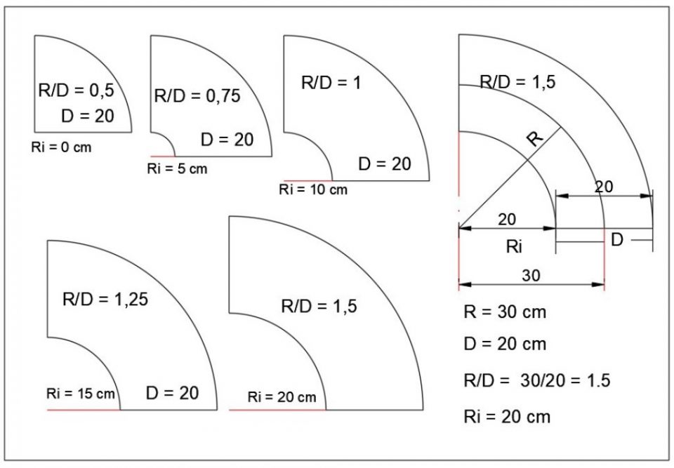
Schematic of the R / D
The shape factor K (ratio between the longer side W and the shorter side D of the pipeline) must normally be less than 2 (never higher than 4), in order to minimize resistance to frictional motion.
The above aspects are all closely related,
With the increase of the aspect ratio K, not only do the resistances due to friction increase, but also the weight of the sheet used in the construction of the duct increases and consequently the purchase price and therefore the installation price.
The trend that is leading towards the standardization of the dimensions of the ducts and the typical shapes of the special pieces is positive, also in the light of the standardization activity carried out by the CEN (European Committee for Standardization).
However, if for the circular ducts the objective has been almost completely achieved, the process relating to the ducts with a quadrangular section appears more complex and articulated: for the latter, in fact, it is necessary to arrive at the definition of dimensional standards for the sizes of the sides ”W” and ”D” of the channeling.
Other free programs of the same kind offered by itieffe ▼
- Air conditioning
- Air ducts
- Ventilation systems
- Autonomous air conditioners
- Psychrometric charts
- Air conditioning tables
- Air quality
- Conditioning diagrams & drawings
Sizing curves for air ducts
The program below is free to use.
To access the reserved version (see below), full page and without advertising, you must be registered.
You can register now by clicking HERE