
Calculation of pipe pressure drops
based on the potential of the system

based on the speed of the water
Calculation of the pressure drop of steel pipes based on the potential and speed expressed in kW, kcal/h, BTU or MJ
In the field of engineering and fluid management, the calculation of pressure drops in steel pipes is of crucial importance. This process is critical to ensuring that fluid conveying systems, which can be found in a wide range of industrial applications, operate efficiently, reliably and economically.
This program was specially created by Itieffe, to provide a complete guide on the necessary calculation. We will explore the fundamental concepts of pressure drops, calculation methodologies, practical tools and best practices used in industry to evaluate, mitigate and manage these losses.
The correct calculation of pressure drops is crucial for engineers, designers, plant operators and all those who work with fluid transport systems. Careful design of steel pipes, which takes pressure drops into account, helps reduce operating costs, optimize energy efficiency and ensure smooth, reliable flow in industrial processes.
With this program, we will guide you through the process, explaining theoretical concepts and providing practical examples. We will also explore how variables such as pipe diameter, fluid velocity, pipe length, and other critical parameters affect it.
We are happy to accompany you on this learning journey, which will equip you with the knowledge and skills necessary to successfully tackle the calculation of pressure losses. Mastery of this skill is critical to ensuring the efficiency and reliability of fluid transportation systems, contributing to success and sustainability in the industrial environment.
Calculation of pipe pressure drops
Easy program that calculates the pressure drop of steel pipes based on the power expressed in kW, kCal / h, BTU or MJ: by inserting the meters, the total pressure drop is obtained.
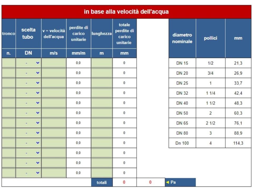
It also performs the same calculation based on the speed of the water: simply by entering the nominal diameter (DN) of the pipe and the speed of the selected water
Results in millimeters / millimeter (mm / m) and in Pascal (Pa)
Instructions
Calculation of pipe pressure drops
Let's analyze the first part of the program

1 - the first thing to do is to identify which unit of measurement will be used to calculate the pressure drop (system capacity: BTU - kcal / h - kW - MJ), in this case kW.
2 - enter the ∆t identified (see table opposite), radiator / radiator system, in this case ∆t 10.
3 - having as an example the following drawing, name the trunks and enter values by inserting in the program only those that end in the most disadvantaged circuit.
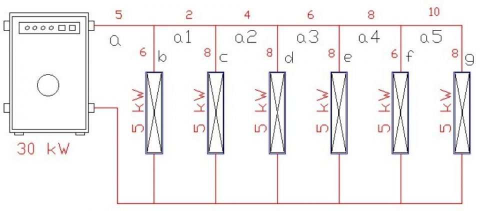
4 - insert the other values into the program by starting to distribute the potential of the plant by branches and entering the indicated values (the value "a”Is that of the potential of the system).

5 - we choose the nominal diameters (DN) of the pipes according to the recommended speeds (see table opposite) and enter the length of the same.
6 - insert the length in meters of the section under examination;
7 - in the final line "totals" we are going to read the pressure drop of the most disadvantaged circuit in mm / m and in Pascal.
End of calculations based on the potential of the system.
PLEASE NOTE: taking into consideration the initial diagram, the pressure drop is calculated only on the delivery line of the pipeline. Enter total lengths for exact calculation.
The users and the generator / chiller are not included in the calculation. Adjust accordingly.
Now let's go to analyze the second part of the program
NB: the following calculation is made exclusively on the basis of the speed of the water required in the section under examination. Potential is not part of the calculations.
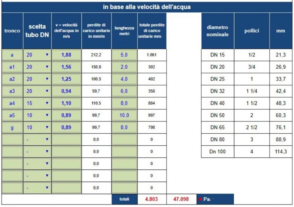
1 - using the same values as in the drawing of the previous example, we are going to perform the calculation based on the water speed.
2 - then enter respectively: the name of the trunk, the chosen DN, the desired speed in the section and the length in meters.
note that by copying the same values between the two parts of the program, the pressure drops remain the same.
PLEASE NOTE: as in the previous diagram, the pressure drop is calculated only on the delivery line of the pipeline. Enter total lengths for exact calculation.
The users and the generator / chiller are not included in the calculation. Adjust accordingly.
Easy right?
good job
Other free programs of the same kind offered by itieffe ▼
- Heating - Plumbing
- Pipelines
- Heating tables
- pumps
- Heating drawing diagrams
- Domestic hot water
- Combustible gases
Calculation of pipe pressure drops
The program below is free to use.
To access the reserved version (see below), full page and without advertising, you must be registered.
You can register now by clicking HERE