
Sizing of millimeter pipes
Calculation of optimal diameter of the pipe in millimeters based on the velocity of the fluid. The capacity can be indicated in: kW, kcal/h, BTU and MJ. Delta t is modifiable.
Welcome to our innovative millimeter pipe sizing program, designed by Itieffe to simplify and streamline the process of choosing the right pipe dimensions based on your specific needs. Pipes play a vital role in a wide range of industries, from engineering and construction to manufacturing and energy. Ensuring that piping is sized correctly is critical to the safety, efficiency, cost-effectiveness and reliability of any system.
Our “Millimeter Pipe Sizing” program is based on advanced calculations and up-to-date technical data, allowing you to precisely select millimeter pipe dimensions based on the specific parameters of your project. Our tool will guide you through the process, taking into account factors such as the potential of the system, which can be expressed in various types of units of measurement and the differential temperature.
The simple interface takes you step-by-step, offering personalized guidance that reflects industry best practices and regulations. You'll save valuable time and reduce the risk of sizing errors that could have costly consequences.
We are confident that our millimeter pipe sizing program will become an indispensable tool in your decision-making process, ensuring the integrity and efficiency of your piping system. We are excited to accompany you on this journey towards more precise and reliable engineering solutions.
Sizing of millimeter pipes
Sizing of millimeter pipes
Process that allows, starting from the potential of the system, to trace the optimal diameter of the pipe based on the speed of the fluid.
The power can be indicated in: kW, kcal / h, BTU and MJ.
The delta t (Δt) is editable.
Instructions

How to proceed
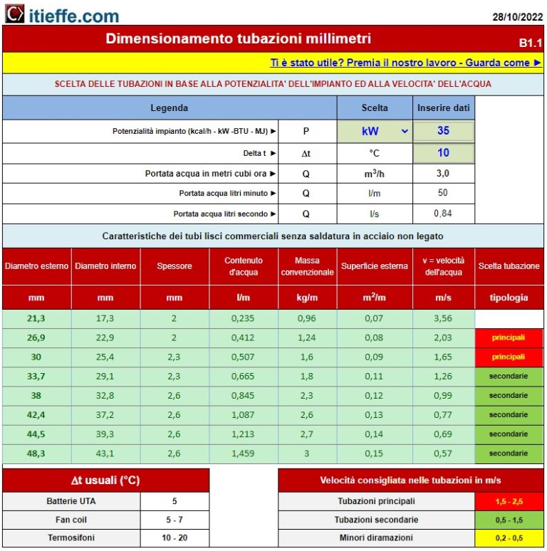
1 - the first thing to do is to choose the unit of measurement in BTU - kW - kcal / h - MJ
2 - insert the plant potential
3 - indicate the Δt (delta t in ° C) referring to the table located in the lower left part (7)
4 - required water flow rate based on capacity and Δt
5 - first line resulting for primary pipe where we go to identify the external diameter of the pipe necessary based on the most suitable water speed, (table at the bottom right 8)
6 - first line resulting for secondary piping where we go to identify the external diameter of the piping required based on the most suitable water speed (table at the bottom right 8)
7 - table indicating the usual Δt
8 - table indicating the speeds in meters per second recommended in the pipes
Let's take the initial drawing as an example
We have a fan coil system with a capacity of 350 kW - the Δt we use is equal to 5 ° C.
Let's read the results:
if the main pipe is branched, the pipe with an external diameter of 114,3 mm can be used with which a water speed of 1.86 m / s is obtained (red box on 5) - as you can see, using smaller diameters, we would have higher speeds which, if too high, would cause dragging noises;
if, on the other hand, we are calculating a secondary branch, the 133 mm pipe (external diameter) can be used, with which a water speed of 1.36 m / s is obtained (green box on 6);
however always refer to the attached table (bottom right 8). For more details on the recommended speeds see: Maximum system water speed.
Easy right?
good job
Other free programs of the same kind offered by itieffe ▼
- Heating - Plumbing
- Pipelines
- Heating tables
- pumps
- Heating drawing diagrams
- Domestic hot water
- Combustible gases
The program below is free to use.
To access the reserved version (see below), full page and without advertising, you must be registered.
You can register now by clicking HERE