
Inertial tank volume calculation
Anti-swing buffer tank volume calculation (thermal flywheel)
This program designed and created by Itieffe is a specialized and useful tool in the field of HVAC (Heating, Ventilation, and Air Conditioning) engineering and in the design of air conditioning systems for residential, commercial or industrial buildings. This software was developed to precisely calculate the volume of the buffer tank (thermal flywheel), a critical component in air conditioning systems to improve their efficiency, thermal stability and ability to respond to load variations. Before examining its main features, it is important to provide a background to understand the context and importance of this software tool.
Context of the Air Conditioning System:
Air conditioning systems play a crucial role in maintaining thermal comfort and air quality in buildings. These systems are widely used in residences, offices, industrial and commercial facilities. Precise design and optimization of these systems are essential to ensure a comfortable and energy-efficient indoor environment.
Importance of Buffer Tank Calculation:
The inertial (anti-swinging) tank, also known as the thermal flywheel, is used in air conditioning systems to accumulate and distribute thermal energy uniformly and efficiently, preventing the refrigeration unit from starting at short intervals.
Program features:
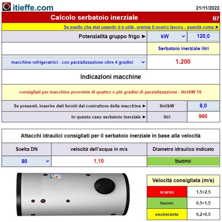
- Data entry: insertion of potential and type of the refrigeration unit.
- Sizing of the inertial tank: calculation of the dimensions, materials and characteristics of the inertial tank necessary to accumulate thermal energy.
- Choice of hydraulic connections: by entering the nominal diameters (DN), you can find the speed of the fluid inside them which allows you to choose the most suitable diameter.
In conclusion, this program is an essential tool for HVAC engineers and designers involved in the design and optimization of air conditioning systems. Its adoption contributes to improving energy efficiency, thermal stability and the quality of the cooling services offered by the systems, ensuring a comfortable and energy-efficient internal environment.
Calculation of anti-swing buffer tank volume (thermal flywheel)
In systems with a reduced water content it is necessary to provide a storage tank so that there are no continuous and rapid changes in temperature in the chilled water as a result of the intermittent regulation (capacity control) and also to limit to a value the number of hourly starts / stops of the electric compressor is acceptable.
By means of different tapping circuits, it is possible to connect several user systems (even with different Δt).
The compensation accumulation (both cold and hot) carried out by means of an inertial tank, also known as anti-oscillation or thermal flywheel, ensures optimal operating conditions of the water chiller unit (also for heat pumps).
It accumulates the surplus supplied by the machine and reduces the frequency of starts (inertial accumulation always necessary on systems with heat pump with Scroll ON / OFF compressor).
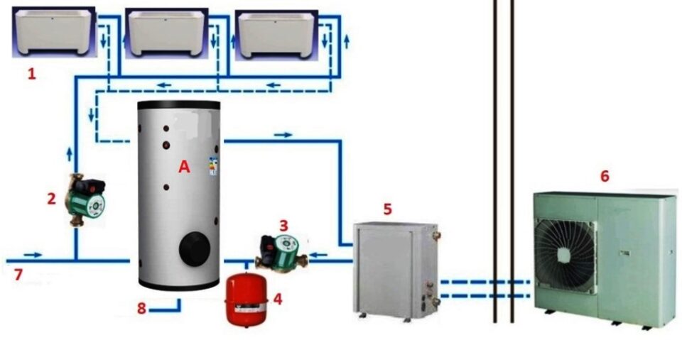
A - buffer tank
1 - fan coil
2 - tapping circulator
3 - primary circulator
4 - expansion vessel
5 - hydronic kit (coolant / water exchanger)
6 - condensing unit with heat pump (chiller)
7 - water supply (from the aqueduct)
8 - tank / circuit drain cock
When inserting an inertial tank on the hydraulic circuit, care must be taken to select it with suitable water inlet and outlet connections (especially for large machines).
They must be proportionate to the potential and therefore to the water flow rate of the machine.
It is always advisable to carry out the sizing calculations with a Δt of 5 ° C (the sizing for the summer regime is always valid also for the winter one but, in some cases, not vice versa).
The program has now been expanded and contains what is necessary to calculate the sections of the hydraulic disconnects of the buffer tank, however, for more details, see the program: "Sizing of steel pipes".
Instructions for using the program
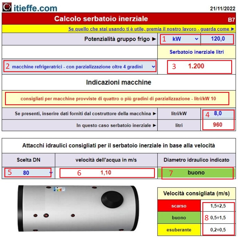
1 – choose the unit of measurement by looking in the drop-down menu and enter the value;
2 – looking in the drop-down menu, enter the type of machine used;
3 – having done this, we can read the capacity that our inertial tank (SI) must have;
4 – some manufacturers directly indicate how many liters are needed per kW – by entering this value in the cell, the capacity of the SI is known;
If we also want to know the dimensions of the hydraulic connections that the SI will have to have without incurring excessive pressure drops and insufficient water flow rates, the program can help us;
5 – insert the Nominal Diameter (DN) of the SI hydraulic connection
6 – here we find the indication of the speed of the water in meters per second based on the selected diameter;
7 – indication of the relevance of the nominal diameter for the speed indicated on the basis of the potential of the plant;
8 – recommended water speeds.
Other free programs of the same kind offered by itieffe ▼
- Heating - Plumbing
- Pipelines
- Heating tables
- pumps
- Heating drawing diagrams
- Domestic hot water
- Combustible gases
Inertial tank volume calculation
The program below is free to use.
To access the reserved version (see below), full page and without advertising, you must be registered.
You can register now by clicking HERE