
Calculation of gas transport piping diameters
Indications on how to calculate the diameter of the pipes used to transport gas from the point of supply to the users
In the vast panorama of gas transport and distribution network engineering, the design of pipes with suitable diameters is a critical step to ensure the efficient and safe flow of fluids. The careful choice of pipe diameters not only impacts the gas transport capacity, but also affects the pressure drop, energy efficiency and overall safety of the system.
The guide to the "Calculation of gas pipeline diameters" was created by Itieffe with the intention of providing an innovative and reliable solution for engineers, designers and professionals in the gas industry. This advanced tool allows you to systematically and precisely address the complexity of designing pipe diameters, allowing you to obtain optimal and well-balanced solutions for gas transmission and distribution systems.
Through careful calculations (see program: Sizing of gas piping networks) and advanced engineering methods, the program offers the possibility to analyze different design scenarios, considering variables such as gas flow, pressure, length of section and characteristics of piping materials.
What usefulness
This tool is designed to guide users in choosing the optimal diameters, taking into account desired performance, acceptable pressure drops and operational safety.
Meeting the challenges of gas pipeline engineering requires specialized skills and appropriate tools. This program is designed to support industry experts and those working in the design of gas distribution networks.
Intuitive interface
Its easy-to-use interface and advanced analytical capabilities offer a practical and sophisticated solution for addressing pipe sizing challenges.
We are excited to introduce this program and to partner with everyone who cares about the efficient, safe and optimized design of gas transportation systems. Our goal is to provide a reliable and versatile tool to support your professional activity and to contribute to the progress of the gas industry.
Calculation of gas transport piping diameters
Sizing can be done in two distinct ways:
- With analytical calculation (Renouard formula or other methods).
- Simplified method with the use of elevations (which we will adopt for the example).
Renouard's formula for low pressure gas networks
Pa - Pb = 232 x 106 x S x L x Q1,82 x D4,82
with:
Pa - Pb = pressure variation (in mm H2O) between the start and end of the pipeline
L = length of the pipeline (km)
Q = flow rate (Sm³/h)
D = internal diameter of the pipe (mm)
S = density of fuel gas (for natural gas the density is 0.5545 being 1 that of air)
Simplified method with the use of elevations
The sizing method of the internal system is indicated in the UNI 7129/08 standard.
The sections of the pipes making up the system must be such as to guarantee a supply of gas sufficient to cover the maximum demand by limiting the pressure loss between the meter and any utilization appliance to values not greater than:
- 0,5 mbar for gases of the 1st family (manufactured gas);
- 1,0 mbar for gases of the 2nd family (natural gas);
- 2,0 mbar for gases of the 3rd family (LPG).
If a pressure regulator is installed upstream of the meter, pressure drops are allowed double those above.
Sizing can take place as follows:
- on the basis of the nominal heat input, shown on the rating plate of the user equipment, the maximum hourly volume flow required for each section of the system is determined;
- the geometric development of the pipes is measured and the equivalent lengths of the special pieces present are added to it, obtaining the virtual lengths.
|
Equivalent lengths of special pieces (m) (See calculation program) |
|||||
|
Natural gas - Arial blends CH4 - Cracking gas |
|||||
|
Internal Ø mm |
90 ° bend |
tee fitting |
cross fitting |
elbow |
tap |
|
<22,3 |
0,2 |
0,8 |
1,5 |
1,0 |
0,3 |
|
by 22,3 to 53,9 |
0,5 |
2,0 |
4,0 |
1,5 |
0,8 |
|
by 53,9 to 81,7 |
0,8 |
4,0 |
8,0 |
3,0 |
1,5 |
|
> 81,7 |
1,5 |
6,5 |
13,0 |
4,5 |
2,0 |
|
Liquefied Petroleum Gas - LPG based mixtures |
|||||
|
Internal Ø mm |
90 ° bend |
tee fitting |
cross fitting |
elbow |
tap |
|
<22,3 |
0,2 |
1,0 |
2,0 |
1,0 |
0,3 |
|
by 22,3 to 53,9 |
0,5 |
2,5 |
5,0 |
2,0 |
0,8 |
|
by 53,9 to 81,7 |
1,0 |
4,5 |
9,0 |
3,0 |
1,5 |
|
> 81,7 |
1,5 |
7,5 |
15,0 |
5,0 |
2,0 |
- on the basis of the relative density of the gas and the type of pipe adopted, the corresponding prospect is chosen and the dimensioning is carried out section by section, adopting for the virtual lengths and flow rates the closest excess values given by the prospectus and from this obtaining the diameter from to adopt.
Calculation of gas transport piping diameters
Example taken from UNI 7129/08 (you see):
Suppose we use a natural gas with a higher calorific value Pcs = kW 10,64 (Hs 38311 kJ / mc) and a lower calorific value Pci = kW 9.6 (Hi = 34560 kJ / mc), with density d = 0,6.
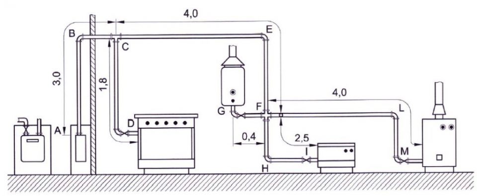
Consider the sizing of an internal system in steel pipe to power the following appliances
Example of internal system
Dimensions in m
Calculation of gas transport piping diameters
BRING
Hob
- nominal thermal Qn= 5,5 kW
- volume Qv = (Qn/Pcs) 5,5/10,64 = 0,5 m³/h
Boiler
- nominal thermal Qn= 15,0 kW
- volume Qv = (Qn/Pci) 15,0/9,6 = 1,6 m³/h
Water heater
- nominal thermal Qn= 18,0 kW
- volume Qv = (Qn/Pci) 18,0/9,6 = 1,9 m³/h
Stove
- nominal thermal Qn= 9,5 kW
- volume Qv = (Qn/Pci) 9,5/9,6 = 1,0 m³/h
- nominal heat S Qn = 48,0 kW
- total volume S Qv = 5,0 m³/h
Note: in the example the hob and the stove are connected to the system with a rigid connection of short length; when calculating the lengths, the use of flexible pipes for connecting the two devices was not taken into account.
In the case of cooking appliances, the higher calorific value of the gas Hs is used (in kJ / m³), in the case of all other appliances the lower calorific value Hi (in kJ / m³)
The sizing proceeds section by section. If, at the end of the calculation, diameters other than those used for the calculation of virtual lengths are found, the sizing must be repeated with a second attempt.
Calculation of gas transport piping diameters
Calculation of virtual pipe length and pipe diameter using elevations
example natural gas in steel tube
Section AC
Thermal capacity Qn = 48,0 kW
Flow rate (Qv) = 5,0 m³ / h
Geometric length of the log C = 3,0 m
Geometric lengths of the longest log AM (measured by the meter and the furthest luminaire fed from the log) = 11,0 m
Calculation of equivalent lengths of special pieces (tap in A = 0.8 m - elbow in B = 1.5 m - T in C = 2.0 m - curve in E = 0.5 m - cross in F = 4.0 m - curve in L = 0.5 m - curve in M = 0.5 m - tap in M = 0.8 m) = 10.6 m
Virtual length of the longest trunk AM (total length increased by the lengths equivalent to changes in direction): 11,0 + 10,6 = 21,6m
From table 2 (natural gas density 0,6 steel pipes), the value of the internal diameter (Øi) is obtained in correspondence with the approximate values for excess of the virtual length and flow rate.
Øi = 27,9 mm (1 ″)
In the same way we proceed for the other sections of the system.
Section CF
Thermal capacity Qn = 42,5 kW
Flow rate (Qv) = 4,50 m³ / h
Geometric length of the trunk CF = 4,0 m
Virtual length of the longest section AM = 21,6 m
Øi = 27,9 mm (1 ″)
FM section
Thermal capacity Qn = 15,0 kW
Flow rate (Qv) = 1,60 m³ / h
Geometric length of the FM section = 4,0m
Virtual length of the longest section AM = 21,6 m
Øi = 22,5 mm (3/4 ″)
Tract CD
Thermal capacity Qn = 5,5 kW
Flow rate (Qv) = 0.50 m³ / h
Geometric length of the trunk CD = 1,8 m
Geometric lengths of the longest section AD = 4,8 m
Calculation of equivalent lengths of special pieces (tap in A = 0,8m - elbow in B = 1,0m - T in C = 0,8 m - elbow in D = 1,0 m - tap in D = 0,3m) = 3,4 m
Virtual length of the longest log AD = (3,4 + 4,8) = 8,2 m
Øi = 13.2 mm (3/8 ″)
Section FG
Thermal capacity Qn = 18,0 kW
Flow rate (Qv) = 1,90 m³ / h
Geometric length of the trunk FG = 0,4 m
Geometric lengths of the longest section AG = 7,4 m
Calculation of equivalent lengths of special pieces (tap in A = 0,8 m - elbow in B = 1,5m - T in C = 2,0 m - curve in E = 0,5 m - cross in F = 4,0 m - tap in G = 0,8m) = 9,6 m
Virtual length of the longest log AG = (7,4 + 9,6) = 17,0 m
Øi = 22,3 mm (3/4 ″)
Section Fl
Thermal capacity Qn = 9,5 kW
Flow rate (Qv) = 1,0 m³ / h
Geometric length of the log Fl = 2,5 m
Geometric lengths of the longest section Al = 9,5 m
Calculation of equivalent lengths of special pieces (tap in A = 0,8 m - elbow in B = 1 m - T in C = 0,8 m - curve in E = 0,2 m - cross in F = 1,5 - curve in G = 0,2 m - tap in G = 0,3 m) = 4,3 m
Virtual length of the longest section Al = (9,5 + 4,3) 13,8 m
Øi = 13,2 mm (3/8 ″)
To calculate the gas distribution network, the program can be used directly:
How to calculate the diameters of the gas transport pipes
Gas flow table according to UNI 7129 - 2008 (You see: GAS UNI 7129 flow rate table)
(excluding tables 1 and 4 - ref. UNI 7129-2001 for manufactured gas)
Table 1
| Volume flow (m15 / h at 0,85 ° C) for manufactured gas, density 0,5 calculated for steel pipes, with pressure drop XNUMX mbar | |||||||||
| Thread | 3/8 | 1/2 | 3/4 | 1 | 1 1/4 | 1 1/2 | 2 | 2,5 | 3 |
| Øi mm | 13,2 | 16,7 | 22,5 | 27,9 | 36,6 | 42,5 | 53,9 | 69,7 | 81,7 |
| smm | 2 | 2,3 | 2,3 | 2,9 | 2,9 | 2,9 | 3,2 | 3,2 | 3,6 |
| Virtual length m | Volume flow m3 / h | ||||||||
|
2 |
1,69 |
3,23 |
7,13 |
13,18 |
27,72 |
41,75 |
80,04 |
161,62 |
246,99 |
|
4 |
1,14 |
2,18 |
4,81 |
8,89 |
18,70 |
28,16 |
53,96 |
109,03 |
168,37 |
|
6 |
0,91 |
1,73 |
3,82 |
7,06 |
14,85 |
22,36 |
42,83 |
86,53 |
133,62 |
|
8 |
0,77 |
1,47 |
3,25 |
6,00 |
12,61 |
18,98 |
36,36 |
73,44 |
113,38 |
|
10 |
0,68 |
1,30 |
2,86 |
5,28 |
11,10 |
16,71 |
32,01 |
64,66 |
99,82 |
|
15 |
0,54 |
1,03 |
2,27 |
4,19 |
8,81 |
13,26 |
25,40 |
51,30 |
79,19 |
|
20 |
0,46 |
0,87 |
1,93 |
3,56 |
7,48 |
11,26 |
21,56 |
43,52 |
67,18 |
|
25 |
0,40 |
0,77 |
1,70 |
3,14 |
6,59 |
9,91 |
18,98 |
38,31 |
59,14 |
|
30 |
0,36 |
0,69 |
1,53 |
2,83 |
5,94 |
8,93 |
17,10 |
34,52 |
53,28 |
|
40 |
0,31 |
0,59 |
1,30 |
2,40 |
5,04 |
7,58 |
14,51 |
29,29 |
45,20 |
|
50 |
0,27 |
0,52 |
1,14 |
2,11 |
4,43 |
6,67 |
12,77 |
25,78 |
39,78 |
|
75 |
0,22 |
0,41 |
0,91 |
1,67 |
3,52 |
5,29 |
10,13 |
20,44 |
31,54 |
|
100 |
0,18 |
0,35 |
0,77 |
1,42 |
2,98 |
4,49 |
8,59 |
17,34 |
26,75 |
Table 2
| Volume flow (m15 / h at 0,6 ° C) for natural gas, density 1 calculated for steel pipes, with XNUMX mbar pressure drop | |||||||||
| Thread | 3/8 | 1/2 | 3/4 | 1 | 1 1/4 | 1 1/2 | 2 | 2,5 | 3 |
| Øi mm | 13,2 | 16,7 | 22,5 | 27,9 | 36,6 | 42,5 | 53,9 | 69,7 | 81,7 |
| smm | 2 | 2,3 | 2,3 | 2,9 | 2,9 | 2,9 | 3,2 | 3,2 | 3,6 |
| Virtual length m | Volume flow m3 / h | ||||||||
| 2 | 3,16 | 5,92 | 13,11 | 23,26 | 47,97 | 71,46 | |||
| 4 | 2,15 | 4,03 | 8,92 | 15,83 | 32,64 | 48,62 | 91,63 | 181,87 | |
| 8 | 1,46 | 2,74 | 6,07 | 10,77 | 22,21 | 33,08 | 62,35 | 123,75 | 189,02 |
| 10 | 1,29 | 2,42 | 5,36 | 9,51 | 19,62 | 29,23 | 55,08 | 109,32 | 166,98 |
| 15 | 1,03 | 1,93 | 4,28 | 7,59 | 15,66 | 23,33 | 43,97 | 87,27 | 133,30 |
| 20 | 0,88 | 1,65 | 3,65 | 6,47 | 13,35 | 19,89 | 37,47 | 74,38 | 113,61 |
| 25 | 0,78 | 1,46 | 3,22 | 5,72 | 11,79 | 17,57 | 33,11 | 65,71 | 100,37 |
| 30 | 0,70 | 1,31 | 2,91 | 5,17 | 10,66 | 15,87 | 29,92 | 59,38 | 90,70 |
| 40 | 0,60 | 1,12 | 2,48 | 4,40 | 9,08 | 13,53 | 25,50 | 50,61 | 77,30 |
| 50 | 0,53 | 0,99 | 2,19 | 3,89 | 8,02 | 11,95 | 22,52 | 44,71 | 68,29 |
| 75 | 0,42 | 0,79 | 1,75 | 3,11 | 6,41 | 9,54 | 17,98 | 35,69 | 54,52 |
| 100 | 0,36 | 0,67 | 1,49 | 2,65 | 5,46 | 8,13 | 15,33 | 30,42 | 46,46 |
Table 3
| Volume flow (mc / h at 15 ° C) for LPG mixtures, density 1,69 calculated for steel pipes, with 2 mbar pressure drop | |||||||||
| Thread | 3/8 | 1/2 | 3/4 | 1 | 1 1/4 | 1 1/2 | 2 | 2,5 | 3 |
| Øi mm | 13,2 | 16,7 | 22,5 | 27,9 | 36,6 | 42,5 | 53,9 | 69,7 | 81,7 |
| smm | 2 | 2,3 | 2,3 | 2,9 | 2,9 | 2,9 | 3,2 | 3,2 | 3,6 |
| Virtual length m | Volume flow m3 / h | ||||||||
| 2 | 2,61 | 489,00 | 10,84 | 19,23 | 39,66 | 59,09 | 111,35 | ||
| 4 | 1,78 | 3,33 | 7,37 | 13,09 | 26,99 | 40,20 | 75,76 | 150,37 | |
| 8 | 1,21 | 2,27 | 5,02 | 8,90 | 18,36 | 27,35 | 51,55 | 102,31 | 156,27 |
| 10 | 1,07 | 2,00 | 4,43 | 7,87 | 16,22 | 24,16 | 45,54 | 90,38 | 138,05 |
| 15 | 0,85 | 1,60 | 3,54 | 6,28 | 12,95 | 19,29 | 36,35 | 72,15 | 110,21 |
| 20 | 0,73 | 1,36 | 3,02 | 5,35 | 11,04 | 16,44 | 30,98 | 61,50 | 93,93 |
| 25 | 0,64 | 1,20 | 2,66 | 4,73 | 9,75 | 14,52 | 27,37 | 54,33 | 82,98 |
| 30 | 0,58 | 1,09 | 2,41 | 4,27 | 8,81 | 13,12 | 24,73 | 49,09 | 74,99 |
| 40 | 0,49 | 0,93 | 2,05 | 3,64 | 7,51 | 11,19 | 21,08 | 41,84 | 63,91 |
| 50 | 0,44 | 0,82 | 1,81 | 3,22 | 6,63 | 9,88 | 18,62 | 36,96 | 56,46 |
| 75 | 0,35 | 0,65 | 1,45 | 2,57 | 5,30 | 7,89 | 14,87 | 29,51 | 45,07 |
| 100 | 0,30 | 0,56 | 1,23 | 2,19 | 4,51 | 6,72 | 12,67 | 25,15 | 38,41 |
Table 4
| Volume flow (m15 / h at 0,85 ° C) for manufactured gas, density 0,5 calculated for copper pipes, with pressure drop XNUMX mbar | |||||||
| Ø mm | 6,0 | 8,0 | 10,0 | 12,0 | 14,0 | 16,0 | 19,0 |
| smm | 1,00 | 1,00 | 1,00 | 1,00 | 1,00 | 1,00 | 1,50 |
| Virtual length m | Volume flow m3 / h | ||||||
| 2 | 0,21 | 0,46 | 0,84 | 1,38 | 2,10 | 3,02 | 4,83 |
| 4 | 0,14 | 0,31 | 0,56 | 0,93 | 1,41 | 2,03 | 3,24 |
| 6 | 0,11 | 0,24 | 0,45 | 0,73 | 1,12 | 1,61 | 2,57 |
| I | 0,09 | 0,21 | 0,38 | 0,62 | 0,95 | 1,36 | 2,17 |
| 10 | 0,08 | 0,18 | 0,33 | 0,55 | 0,83 | 1,20 | 1,91 |
| 15 | 0,07 | 0,14 | 0,26 | 0,43 | 0,66 | 0,95 | 1,51 |
| 20 | 0,06 | 0,12 | 0,22 | 0,37 | 0,56 | 0,80 | 1,28 |
| 25 | 0,05 | 0,11 | 0,20 | 0,32 | 0,49 | 0,71 | 1,13 |
| 30 | 0,04 | 0,10 | 0,18 | 0,29 | 0,44 | 0,64 | 1,02 |
| 40 | 0,04 | 0,08 | 0,15 | 0,25 | 0,37 | 0,54 | 0,86 |
| 50 | 0,03 | 0,07 | 0,13 | 0,22 | 0,33 | 0,47 | 0,76 |
| 75 | 0,03 | 0,06 | 0,10 | 0,17 | 0,26 | 0,38 | 0,60 |
| 100 | 0,02 | 0,05 | 0,09 | 0,15 | 0,22 | 0,32 | 0,51 |
Table 5
| Volume flow (mc / h at 15 ° C) for natural gas, density 0,6 calculated for copper pipes, with 1 mbar pressure drop | ||||||||||
| Ø and mm | 12 | 14 | 15 | 16 | 18 | 22 | 28 | 35 | 42 | 54 |
| Øi mm | 10 | 12 | 13 | 14 | 16 | 20 | 26 | 33 | 39 | 51 |
| smm | 1,0 | 1,0 | 1,0 | 1,0 | 1,0 | 1,0 | 1,0 | 1,0 | 1,5 | 1,5 |
| Virtual length m | Volume flow m3 / h | |||||||||
| 2 | 1,51 | 2,45 | 3,04 | 3,70 | 5,28 | 9,57 | 19,27 | 36,40 | 56,83 | |
| 4 | 1,03 | 1,67 | 2,07 | 2,52 | 3,59 | 6,51 | 13,11 | 24,77 | 38,67 | 79,07 |
| 8 | 0,70 | 1,14 | 1,41 | 1,71 | 2,44 | 4,43 | 8,92 | 16,85 | 26,31 | 53,80 |
| 10 | 0,62 | 1,00 | 1,24 | 1,51 | 2,16 | 3,92 | 7,88 | 14,89 | 23,24 | 47,53 |
| 15 | 0,49 | 0,80 | 0,99 | 1,21 | 1,72 | 3,13 | 6,29 | 11,88 | 18,55 | 37,94 |
| 20 | 0,42 | 0,68 | 0,84 | 1,03 | 1,47 | 2,66 | 5,36 | 10,13 | 15,81 | 32,34 |
| 25 | 0,37 | 0,60 | 0,75 | 0,91 | 1,30 | 2,35 | 4,74 | 8,95 | 13,97 | 28,57 |
| 30 | 0,33 | 0,54 | 0,67 | 0,82 | 1,17 | 2,13 | 4,28 | 8,09 | 12,62 | 25,81 |
| 40 | 0,29 | 0,46 | 0,57 | 0,70 | 1,00 | 1,81 | 3,65 | 6,89 | 10,76 | 22,00 |
| 50 | 0,25 | 0,41 | 0,51 | 0,62 | 0,88 | 1,60 | 3,22 | 6,09 | 9,50 | 19,44 |
| 75 | 0,20 | 0,33 | 0,41 | 0,49 | 0,71 | 1,28 | 2,57 | 4,86 | 7,59 | 15,52 |
| 100 | 0,17 | 0,28 | 0,35 | 0,42 | 0,60 | 1,09 | 2,19 | 4,14 | 6,47 | 13,22 |
Table 6
| Volume flow (m15 / h at 1,69 ° C) for LPG mixtures, density 2 calculated for copper pipes, with XNUMX mbar pressure drop | ||||||||||
| Ø and mm | 12 | 14 | 15 | 16 | 18 | 22 | 28 | 35 | 42 | 54 |
| Øi mm | 10 | 12 | 13 | 14 | 16 | 20 | 26 | 33 | 39 | 51 |
| smm | 1,0 | 1,0 | 1,0 | 1,0 | 1,0 | 1,0 | 1,0 | 1,0 | 1,5 | 1,5 |
| Virtual length m | Volume flow m3 / h | |||||||||
| 2 | 1,25 | 2,03 | 2,51 | 3,06 | 4,37 | 7,92 | 15,94 | 30,09 | 46,98 | |
| 4 | 0,85 | 1,38 | 1,71 | 2,08 | 2,97 | 5,39 | 10,84 | 20,48 | 31,97 | 65,37 |
| 8 | 0,58 | 0,94 | 1,16 | 1,42 | 2,02 | 3,66 | 7,38 | 13,93 | 21,75 | 44,48 |
| 10 | 0,51 | 0,83 | 1,03 | 1,25 | 1,79 | 3,24 | 6,52 | 12,31 | 19,21 | 39,29 |
| 15 | 0,41 | 0,66 | 0,82 | 1,00 | 1,43 | 2,58 | 5,20 | 9,83 | 15,34 | 31,37 |
| 20 | 0,35 | 0,56 | 0,70 | 0,85 | 1,21 | 2,20 | 4,43 | 8,37 | 13,07 | 26,73 |
| 25 | 0,31 | 0,50 | 0,62 | 0,75 | 1,07 | 1,95 | 3,92 | 7,40 | 11,55 | 23,62 |
| 30 | 0,28 | 0,45 | 0,56 | 0,68 | 0,97 | 1,76 | 3,54 | 6,68 | 10,44 | 21,34 |
| 40 | 0,24 | 0,38 | 0,48 | 0,58 | 0,83 | 1,50 | 3,02 | 5,70 | 8,90 | 18,19 |
| 50 | 0,21 | 0,34 | 0,42 | 0,51 | 0,73 | 1,32 | 2,67 | 5,03 | 2,86 | 16,07 |
| 75 | 0,17 | 0,27 | 0,34 | 0,41 | 0,58 | 1,06 | 2,13 | 4,02 | 6,27 | 12,83 |
| 100 | 0,14 | 0,23 | 0,29 | 0,35 | 0,50 | 0,90 | 1,81 | 3,42 | 5,35 | 10,93 |
Table 7
| Volume flow (m15 / h at 0,6 ° C) for natural gas, density 1 calculated for polyethylene pipes, with XNUMX mbar pressure drop | ||||||||
| Ø and mm | 25 | 32 | 40 | 50 | 63 | 75 | 90 | 110 |
| Øi mm | 19 | 26 | 34 | 44 | 55,8 | 66,4 | 79,6 | 97,4 |
| smm | 3,0 | 3,0 | 3,0 | 3,0 | 3,6 | 4,3 | 5,2 | 6,3 |
| Virtual length m | Volume flow m3 / h | |||||||
| 2 | 8,35 | 19,27 | 39,42 | |||||
| 4 | 5,68 | 13,11 | 26,82 | 53,34 | 100,50 | 159,81 | ||
| 8 | 3,87 | 8,92 | 18,25 | 36,29 | 68,38 | 108,73 | 176,34 | 302,04 |
| 10 | 3,42 | 7,88 | 16,12 | 32,06 | 60,41 | 96,06 | 155,78 | 266,83 |
| 15 | 2,73 | 6,29 | 12,87 | 25,59 | 48,22 | 76,68 | 124,36 | 213,01 |
| 20 | 2,32 | 5,36 | 10,97 | 21,81 | 41,10 | 65,36 | 105,99 | 181,55 |
| 25 | 2,05 | 4,74 | 9,69 | 19,27 | 36,31 | 57,74 | 93,63 | 160,38 |
| 30 | 1,86 | 4,28 | 8,76 | 17,41 | 32,81 | 52,17 | 84,61 | 144,93 |
| 40 | 1,58 | 3,65 | 7,46 | 14,84 | 27,97 | 44,47 | 72,12 | 123,52 |
| 50 | 1,40 | 3,22 | 6,59 | 13,11 | 24,70 | 39,28 | 63,71 | 109,12 |
| 75 | 1,11 | 2,57 | 5,26 | 10,47 | 19,72 | 31,36 | 50,86 | 87,11 |
| 100 | 0,95 | 2,19 | 4,49 | 8,92 | 16,81 | 26,73 | 43,35 | 74,25 |
Table 8
| Volume flow (m15 / h at 1,69 ° C) for LPG mixtures, density 2,0 calculated for polyethylene pipes, with XNUMX mbar pressure drop | ||||||||
| Ø and mm | 25 | 32 | 40 | 50 | 63 | 75 | 90 | 110 |
| Øi mm | 19 | 26 | 34 | 44 | 55,8 | 66,4 | 79,6 | 97,4 |
| smm | 3,0 | 3,0 | 3,0 | 3,0 | 3,6 | 4,3 | 5,2 | 6,3 |
| Virtual length m | Volume flow m3 / h | |||||||
| 2 | 6,90 | 15,94 | 32,59 | 64,81 | 122,12 | |||
| 4 | 4,70 | 10,84 | 22,17 | 44,10 | 83,09 | 132,12 | 214,27 | 367,02 |
| 8 | 3,20 | 7,38 | 15,09 | 30,00 | 56,54 | 89,90 | 145,79 | 249,72 |
| 10 | 2,82 | 6,52 | 13,33 | 26,51 | 45,94 | 79,42 | 128,79 | 220,60 |
| 15 | 2,25 | 5,20 | 10,64 | 21,16 | 39,87 | 63,40 | 102,82 | 176,11 |
| 20 | 1,92 | 4,43 | 9,07 | 18,03 | 33,98 | 54,03 | 87,63 | 150,10 |
| 25 | 1,70 | 3,92 | 8,01 | 15,93 | 30,02 | 47,73 | 77,41 | 132,60 |
| 30 | 1,53 | 3,54 | 7,24 | 14,40 | 27,13 | 43,14 | 69,96 | The 19,83 |
| 40 | 1,31 | 3,02 | 6,17 | 12,27 | 23,12 | 36,76 | 59,62 | 102,13 |
| 50 | 1,15 | 2,67 | 5,45 | 10,84 | 20,43 | 32,48 | 52,67 | 90,22 |
| 75 | 0,92 | 2,13 | 4,35 | 8,65 | 16,31 | 25,93 | 42,05 | 72,02 |
| 100 | 0,79 | 1,81 | 3,71 | 7,38 | 13,90 | 22,10 | 35,84 | 61,38 |
Calculation of gas transport piping diameters
Other free programs of the same kind offered by itieffe ▼
- Heating - Plumbing
- Pipelines
- Heating tables
- pumps
- Heating drawing diagrams
- Domestic hot water
- Combustible gases