
Indications on how air ducts for ventilation systems are designed
The study and design of air ducts for conditioning represent a critical and essential phase in the design of effective and efficient ventilation and HVAC (Heating, Ventilation, and Air Conditioning) systems. The importance of a guide that provides detailed instructions on how to conduct this process cannot be emphasized enough.
First, proper duct design is essential to ensure that a building or facility is adequately supplied with fresh air and that conditioned air is distributed evenly. A guide explaining in detail how to conduct an accurate preliminary study and a design of the air ducts allows engineers and architects to correctly size the systems, avoiding over- or under-sizing which can lead to energy waste and additional costs.
Adequate design
Additionally, proper air duct design is critical to thermal comfort and indoor air quality. Poorly designed or poorly positioned ducts can cause temperature dispersions and irregular air flows, leading to uncomfortable conditions for the occupants also due to annoying noise. Detailed guidance can help minimize these problems, ensuring that air is distributed consistently and thermal comfort levels are optimal.
Energy point of view
From an energy point of view, the efficiency of an HVAC system is directly related to the design of the air ducts. Well-designed channels and ducts reduce pressure drop and allow for more efficient air distribution, thus reducing energy consumption and long-term operating costs. This is particularly important in the current context of growing attention towards environmental sustainability and energy efficiency.
Finally, proper air duct design helps ensure optimal indoor air quality. This is essential for the health and well-being of the occupants, as poor air circulation can lead to the accumulation of pollutants and allergens, with possible consequences for respiratory health.
In conclusion, a detailed guide on how to carry out the study and design of air conditioning ducts is essential for the correct design and effective operation of HVAC systems. This guide, created by Itieffe, offers a solid basis for ensuring energy efficiency, comfort, indoor air quality and long-term savings, thus helping to create healthier, more sustainable and comfortable environments.
Air duct project study
STUDY AND PROJECT OF AIR DUCTS
For the calculation of a ventilation system that requires air ducts it is necessary to follow an ordered procedure which can be schematized as follows.
1) A careful study of the building plan and the building itself. in order to design the most convenient plant. avoiding as much as possible all obstacles and ensuring all necessary access to its component parts. At the same time making sure that the project is simple and that it includes wide curves and gradual variations in section.
2) A location of the duct outlets such as to ensure appropriate air distribution in the room to be ventilated.
3) Determine the size of the outlets based on the volume of air required. their number and the permitted speed. in order to obtain the desired launch. not forgetting. however, that as the speed increases the noise also increases and making sure that all the vents have an adequate free surface.
4) Calculate the dimensions of all main ducts and branches using one of the following two methods:
- a) method based on speed: by pre-setting the speed of the air in the different points of the circuit starting from its maximum value in the main duct to its minimum at the outlet into the environment
- b) method based on equal resistance: the duct is proportioned so as to obtain an equal loss of pressure due to friction per unit of development of the duct.
SPEED OF THE AIR IN THE DUCTS
|
Location |
civil buildings m / s |
industrial environments m / s |
|
He took in fresh air |
4 – 5 |
6 – 8 |
|
Main duct connected to the fan |
4 – 5 |
6 – 12 |
|
Branches of the duct |
2 – 5 |
3 – 6 |
|
Vertical branches |
1,5 – 3 |
2 – 4 |
|
Vents, grills, etc. |
0,5 – 2 |
1 – 5 |
In industrial environments, higher air speeds are allowed, because the resulting noise is a negligible factor.
A similar consideration can be made for other particular environments. Normally, the distribution of the air from the fan to the outlets is carried out, first with a main manifold and then with single branches, rather than with more ducts belonging to the fan separately, and this for obvious reasons of economy on the cost of the plant.
SPEED-BASED METHOD
This method, to establish the dimensions of the air ducts, involves the arbitrary choice of the speeds in the different sections of the system, starting, as mentioned, from the highest speeds near the fan to arrive, with progressive reductions, at the speeds lower in the various branches and therefore in the grilles or vents that introduce the air into the room to be ventilated.
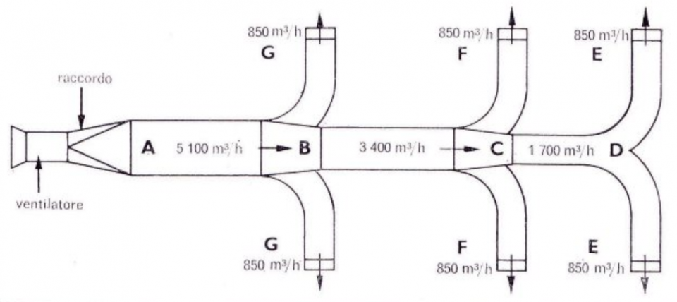
Example 1
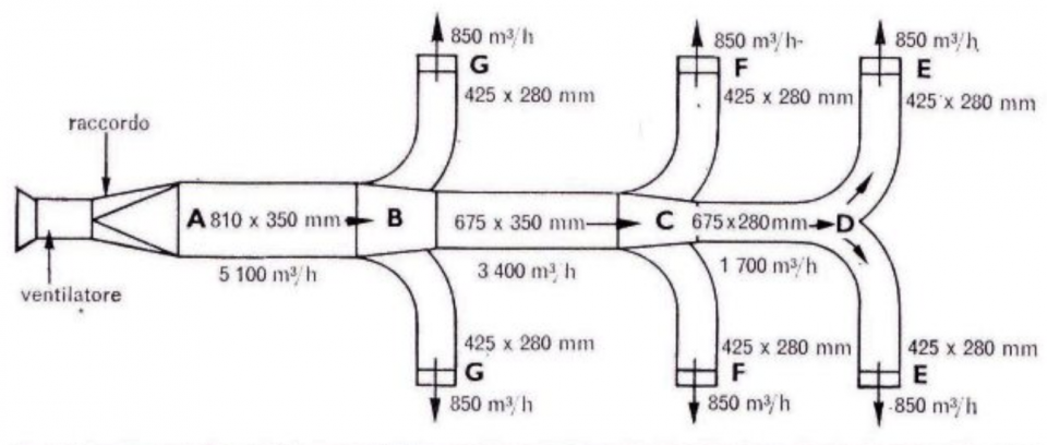
Figure 1 shows a simple system, intended for a civil environment, equipped with six 850 m inlet vents3/ h each in points EE, FF, GG.
The plant, therefore, will be calculated for one flow rate total air of 6 x 850 = 5.100 m3/ H.
The main duct is given by the sections ABC D.
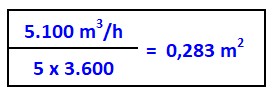
Section AB of the main duct
This section carries 5.100 m3/ h and assuming that noise is a negligible factor, the speed in this trunk can be 5 m / s.
Section surface AB
BC section of the main duct
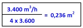
Here the noise factor becomes more important and it is good to adopt a speed of 4 m / s. This section carries 5.100 m3/ h, minus the air derived from the two BG arms, i.e. 5.100 - 1.700 = 3.400 m3/ H.
BG section surface
CD section of the main duct
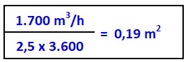
As this section of the main duct is away from the fan and only supplies the two arms DE. the appropriate speed and 2,5 m / s.
This section carries 5.100 m3/ h minus the air derived in the four arms BG and CF, i.e. 5.100 - (1700 - 1.700) = 1.700 m3/ H.
Surface of the CD section
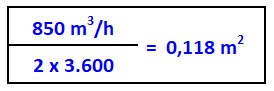
Derivation DE
Since there is only one outlet E at each branch, the two sections of duct will have the same dimensions and assuming that the most appropriate speed is 2 m / s for a range of 850 m3/ h we will have:
Section surface DE
Now, having known the areas of the sections of the ducts, the actual dimensions can be established, bearing in mind that for ease of construction it is advisable, in correspondence with each section variation, to vary only one of the two dimensions.
In the example considered, the suitable dimensions could be:
AB = 810 X 350 mm = 0,283 m2
BC = 675 X 350 mm = 0,236 m2
CD = 675 X 280 mm = 0,189 m2
DE = 425 X 280 mm = 0,119 m2
METHOD BASED ON THE EQUAL RESISTANCE
This method, for establishing the dimensions of the air ducts, is probably better than the previous method; it aims to ensure a good distribution especially in those plants that have a considerable development in length.
With it, moreover, it is not necessary, at least to a certain extent, a certain experience to determine the most suitable speeds in the different parts of the plant; only one speed must be established a priori: that in the last section of the system.
Once the dimensions of this section have been fixed, the other speeds are calculated in such a way as to have the same pressure drop per unit length of the duct.
The diagram in Figure 4. gives the pressure loss in mm cda [or kg / m2) for circular ducts of different sizes and carrying the indicated quantities of air; it is possible to read the pressure drop for a given section and, therefore, the dimensions of the other sections of duct can be established by reading the diameter corresponding to the same pressure drop based on the respective air flow.
On the basis of table 1. it is also possible to obtain the diameters of the equivalent circular ducts, knowing the dimensions of the sides of the rectangular ducts and vice versa.
Example 2
Starting from the DE duct, considered in the example already mentioned, and assuming a speed of 2 m / s:
duct size:

Equivalent circular duct diameter = 0,388 m.
From the diagram in figure 4, the pressure drop for 1 m of duct is equal to 0,013 mm cda
The CD conduit carries 1700 m3/ h, the pressure drop for a length of 1 m is 0,013 mm cda
Diameter of the equivalent circular duct = 500 mm.
The BC duct carries 3.400 m3/ h, the pressure drop for 1 m is always 0,013 mm cda
Equivalent circular duct diameter = 650 mm.
The AB duct carries 5.100 m3/ h, the pressure drop for I in is always 0,013 mm cda
Equivalent circular duct diameter = 770 mm.
We have thus established the dimensions of the channels, assuming that they are made up of circular section ducts. To obtain the corresponding rectangular ducts, table l can be used by adopting the following proportions.
|
Conducted |
Ø mm |
Approximate equivalent rectangular duct |
|
DE Ø |
388 |
X 400 320 |
|
CD Ø |
500 |
X 680 320 |
|
BC Ø |
650 |
X 680 520 |
|
AB Ø |
770 |
X 960 520 |
It should be noted that this method simply establishes the dimensions of the system ducts; from this it does not automatically follow that each nozzle has the exact pre-established quantity of air.
The outlets closest to the fan may give a little more air than those located at the ends of the system.
In this sense, a more precise design of the system would involve long calculations and, in all probability, fractional dimensions of the ducts.
In cases where exact air distribution is essential, it is completely normal to use dampers that allow you to regulate the flow rates in the individual branches.
Finally, it is necessary to be very careful in sizing curves, section changes, in evaluating obstacles, etc., in order to keep the pressure drop in the system as low as possible and to achieve power savings in the operation of the fan.
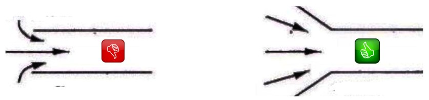
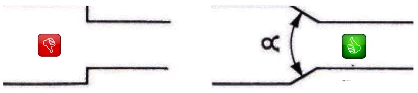
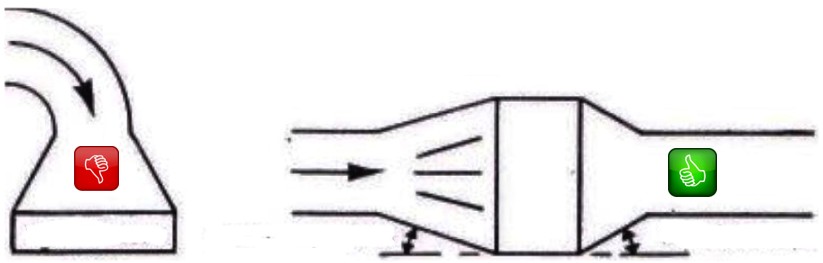
Figure 3. gives some examples of elements making up the ventilation systems in their possible situations.
CONVERSION OF DYNAMIC PRESSURE IN STATIC PRESSURE
In many cases, the fan chosen for a given duct network is a small fan with a high rotation speed and high air delivery speed.
This results in high dynamic pressure and therefore high kinetic energy.
In these cases it is advisable that this energy be reused to increase the performance of the fan rather than letting it dissipate.
This can be achieved if, before the final discharge of the air, the speed of the air itself is conveniently reduced with a minimum loss, until the dynamic pressure is reasonably low.
The energy thus recovered increases the static pressure developed by the fan.
In practice, this is achieved by using a diverging duct, called diffuser, having a final diameter which is a function of the desired discharge speed.
The angle of divergence is important; the possibilities of recovering the kinetic energy depend on it, but the space occupied and the cost of the diffuser itself should not be neglected.
In general it can be said that in a speaker the total divergence angle should not exceed 10 ° to obtain a good recovery, while it is completely useless if its opening is 60 ° or more.
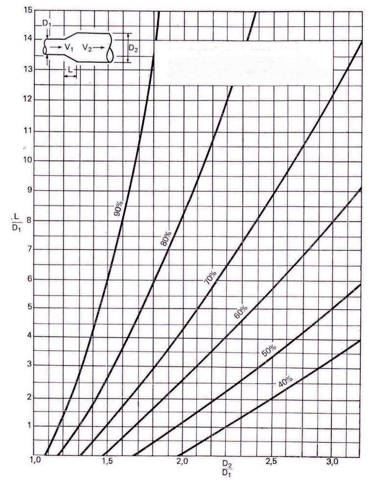
The diagram in figure 5 indicates the optimal proportions and dimensions, for diffusers placed on the delivery of a fan, corresponding to different recovery percentages of the dynamic pressure of the fan.
The same principle can be applied when the fan does not discharge with a free mouth, but feeds a network of ducts, with the difference that the dynamic pressure of the moving air is not lost at the end of the diffuser but is maintained in the duct that follows it. .
Consequently, any recovery of static pressure is due to the difference in dynamic pressure at the two ends of the diffuser itself.
Figure 6. indicates the percentage of static pressure recovery in the diffuser based on the difference in dynamic pressure at each of its ends, when there are no exhaust leaks.
Example 3
A system with canalized air is: foreseen for the conveyance of 8.500 m3/ h at a static pressure of 18 mm cda You want to use an axial fan with blades with a wing profile of about 480 mm in diameter with:
a range of 8.500 m3/ h, a static pressure of 13 mm cda and a total pressure of 23 mm cda What are the dimensions of the diffuser necessary to obtain the desired static pressure of 18 mm cda?
Dynamic pressure = Total pressure - Static pressure: 23 - 13 = 10 mm cda
Static pressure recovery desired = 18 - 13 = 5 mm.
If the fan is completely downstream from the system, i.e. it discharges with its mouth free, the required recovery percentage will be:
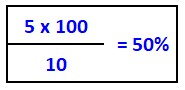
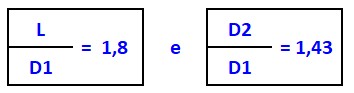
From figure 5 the optimal dimensions of a diffuser that gives a recovery of 50% are:
where:
L = length of the diffuser
D1 = diameter of the diffuser end (fan side)
D2 = diameter of the diffuser end (exhaust side)
and therefore:
L = 1,80 X 480 mm = 865 mm approximately
D = 1,43 X 480 mm = approximately 685 mm.
Figure 3
EXAMPLES OF CORRECT AND INCORRECT DISTRIBUTION OF PARTS OF AIR DUCTS
Entry into the conduit
Reduction and enlargement of section
Curves and derivations
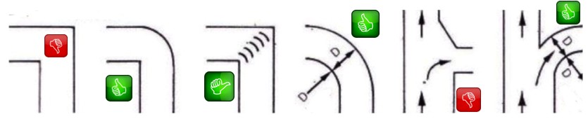
table 1
Air ducts - equivalent diameter
Figure 4
Pressure drops in straight circular galvanized sheet pipes - air at 20 ° C and 760 mm Hg
Range in m3/h
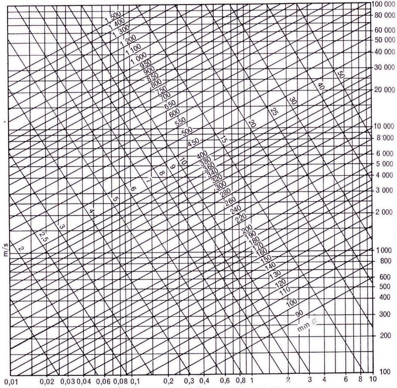
Figure 5
Optimal dimensions of the diffusers in the delivery of a fan for different percentages of dynamic pressure recovery
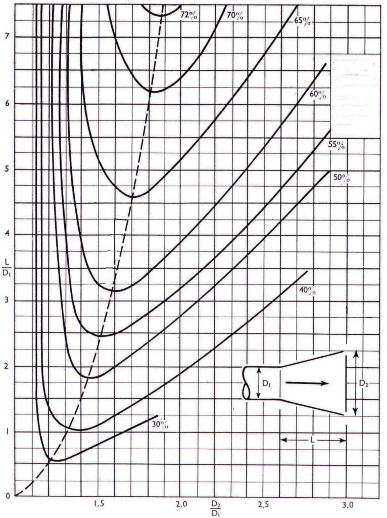
Static pressure recovery in% of the dynamic pressure in section D
Figure 6
Static pressure recovery expressed as a% of the difference between the dynamic pressures at the two ends of the diffuser
Static pressure recovery in the diffusers expressed as a% of the difference in dynamic pressures
Other free programs of the same kind offered by itieffe ▼
- Air conditioning
- Air ducts
- Ventilation systems
- Autonomous air conditioners
- Psychrometric charts
- Air conditioning tables
- Air quality
- Conditioning diagrams & drawings