Refrigeration circuit - The basics
Basic information on the operation of the refrigeration circuit, the components used and the parts involved
Welcome to this guide created by Itieffe "Exploring the controlled cold - guide to the basics of the refrigeration circuit". In a world where temperature control is essential for a wide range of applications, this guide will take you on a fascinating journey into the heart of refrigeration circuits, revealing the secrets behind the functioning of these systems that allow us to generate and maintain cold .
Refrigerant circuits are present in many aspects of our daily life, from homes to industrial plants, from supermarkets to scientific laboratories. But what actually happens inside these circuits that allow us to cool and keep things at controlled temperatures? In this guide, we will explore the fundamental foundations of refrigerant circuits, demystifying the key concepts that make them possible.
Through a clear and accessible approach, we will guide you through the thermodynamic principles that underlie the operation of a refrigeration circuit. You will learn how the refrigerant fluid, subjected to pressure and temperature variations, can transfer heat from one environment to another, allowing temperatures to be reached lower than those of the surrounding environment. Through diagrams, detailed explanations and practical examples, we will take you through the steps that make up a refrigeration cycle.
Refrigeration circuit - The basics
This guide does not require advanced knowledge of thermodynamics or engineering. It is intended for those who wish to have a basic understanding of how refrigeration circuits work and how they are used in a variety of contexts. Whether you're a student, a technician, or just curious to learn something new, we hope this guide will shed light on the complex but fascinating world of refrigerant circuits.
We invite you to join us on this journey through controlled cold, where the laws of thermodynamics translate into technologies that influence our comfort, our health and the production of essential goods. May this guide be your compass as you explore the mechanisms that allow us to master the cold and use it to our advantage.
THE REFRIGERANT CIRCUIT
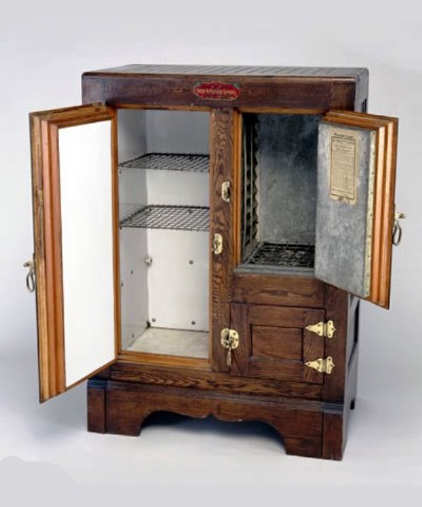
There are no machines that are able to produce cold, but there are machines that are able to subtract heat from fluids or bodies (air, water, metals, etc.).
These machines are generically called: "refrigerators".
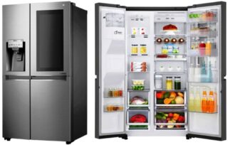
They are divided into categories based on their type and use and are called domestic refrigerators and freezers (temperatures +4 -20 ° C), industrial and laboratory refrigerators (temperatures up to -140 ° C) dehumidifiers, air conditioners and water chillers of any size and potential.
Let's analyze these machines (in this case we will take the small domestic refrigeration into consideration even if the bases are the same for all categories).
Refrigeration circuit - The basics
THE REFRIGERATOR: STANDARD STEAM COMPRESSION CYCLE
Heat is known to transfer from higher temperature areas to lower temperature areas. This heat transfer process occurs spontaneously in nature, without requiring the intervention of any machine. The reverse process, on the other hand, ie the transfer of heat from lower temperature areas to higher temperature areas, does not occur spontaneously and requires the use of special machines called refrigeration machines.
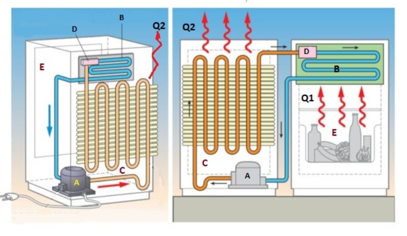
Figure 1 shows the system diagram of a standard vapor compression refrigeration circuit.
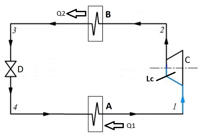
A = evaporator
B = capacitor
C = compressor
D = expansion valve or capillary tube (lamination organ)
Q2 = condensation heat released to external air (or other fluids)
Q1 = heat removed from the environment (or from the fluid interested)
Lc = compression work (necessary expense).
Cooling circuit transformations
The transformations carried out by the refrigerant fluid inside the refrigeration unit can be traced back to the indications of the "Carnot cycle" of which we refer the explanation to other locations:
1_2 – The low pressure saturated steam is sucked in by the compressor and undergoes reversible adiabatic compression (isoentropic compression). The compressor compresses the vapor, increasing its pressure and temperature and pushing it into the condenser.
2_3 – The heat Q2, heat of condensation, is transferred to the external air or to other fluids, in a condensation process at constant pressure, transforming the vapor into a liquid. The exchanger that carries out the transformation is called a condenser. A fluid comes out of the condenser in the form of a saturated liquid.
3_4 – There is passage through the expansion valve (lamination valve), in which the fluid passes from the higher pressure to the lower pressure producing the expansion phenomenon. It is with this change of state that heat is removed from the environment or fluid. The liquid, after the expansion valve, is no longer compressed and returns to the vapor state.
4_1 – The heat Q1 (heat removed from the environment or the fluid involved) is received by the refrigeration system at a lower temperature in an evaporation process at constant pressure through a heat exchanger called evaporator, in this way the cycle closes and the refrigerant and ready to perform a new refrigeration cycle.
Let's try to understand the functioning of the refrigeration circuit
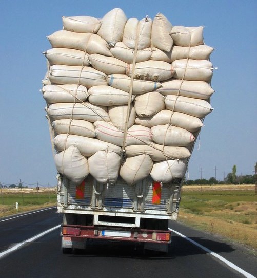
One can imagine the operating principle of a refrigeration circuit like a large truck running inside a closed circuit such as the Grande Raccordo Anulare of Rome.
Upon departure, the truck (figure 2) is loaded with heat taken from the Aurelia exit of the GRA (which in our case could be a room to be air-conditioned). The truck travels south along the GRA to discharge the heat at the Casilina exit (which in our case is the external environment). At this point the truck runs along the stretch of the GRA in the opposite direction to return to the Aurelia exit and load more heat.
The Aurelia output is called the evaporator while the Casilina output is called the condenser.
COP REFRIGERATING MACHINES
For refrigeration machines, it is possible to define an efficiency indicator: the Coefficient of Performance (COPF):
COPF = profit effect / necessary expense = Q1 / Lc
where the useful effect is the heat subtracted at low temperature to maintain a cold environment, while the necessary expense is represented by the compression work.
The COPF and inversely proportional to the operating cost of the plant: the higher the compression work, the lower the coefficient of performance.
SUB-COOLING AND OVERHEATING
In common practice, in standard vapor compression cycles a sub-cooling of the liquid is performed before carrying out the expansion (lamination). In this way it is sure to feed the lamination member with liquid and not with steam (which would make the device work badly). The superheating is done to be sure to feed the compressor with steam and to avoid that the fluid contains traces of liquid. In fact, it can happen in this case that the compressor compresses some liquid causing it to break. It is therefore preferred that the fluid be slightly overheated at the compressor inlet. This operation is always performed in the refrigeration cycle regardless of whether there is an increase or decrease in COP; in this way you can be sure that the compressor (very expensive organ) works well and for a long time.
BEHAVIOR SCHEMATIZATION
The figure shows a diagram of a generic refrigeration circuit: it can be seen how the air in contact with the evaporator B releases heat Q1 coming from the environment E, while other external air is warmer (but always at a lower temperature than the condensation temperature) it heats up passing through the condenser C and is then sent outside (heat Q2). The circuit is completed by the rolling element D.
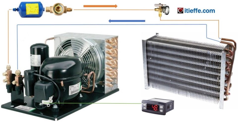
COMPONENTS OF THE REFRIGERANT CIRCUIT
THE COMPRESSOR
The compressor is the “heart” of the refrigeration circuit. It is the driving force of the refrigeration system because it provides the work necessary to carry out the thermodynamic cycle. Its function is to bring the vaporized refrigerant fluid from the evaporator pressure (low pressure) to the condenser pressure (high pressure) which corresponds to a condensation temperature compatible with that of the external cooling fluid (air or water).
Types of refrigeration compressors
|
alternative |
hermetic |
|
semi-hermetic |
|
|
open |
|
|
rotary |
screw |
|
single screw |
|
|
double screw |
|
|
spiral (scroll) |
|
|
vanes (sliding vane) |
|
|
swing piston |
There are different types of compressors that can be classified by type of compression and construction type:
- dynamics in which compression is obtained by varying the flow conditions of the fluid with energy conversion
- volumetric in which the compression is obtained by mechanical reduction of the volume offered to the fluid in a capsulism with variable geometry; they are divided into:
Reciprocating Volumetric Compressors
The reciprocating compressor is essentially constituted by a cylinder inside which a piston runs, with reciprocating motion. The cylinder is closed in the upper part by a plate where two openings equipped with valves are obtained. They allow the cylinder to be connected alternatively, via the suction duct, to the evaporator and, via the delivery duct, to the condenser. By means of a connecting rod and crank mechanism, the piston is connected to the crank shaft which has the function of transforming the rotary motion of the engine to which it is connected in an alternative way (generally an electric motor).
Diagram of the cylinder piston valves system
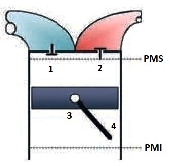
TDC = top dead center
PMI = bottom dead center
1 = suction valve
2 = delivery valve
3 = piston
4 = connecting rod
During the intake phase, the piston moves downwards, the intake valves open, putting the cylinder chamber in communication with the low pressure area of the circuit. Once the useful volume has been reached, the one that occurs at the lower dead center (PMI), the piston begins to reduce the volume of the cylinder chamber and to compress the fluid. The intake valves close, while the delivery valves open only when the pressure inside the cylinder equals that present in the upper part of the circuit. The compression ratio (and the symbol ρ is indicated) is the ratio between the condensation pressure and the evaporation pressure.
The reciprocating compressors can in turn be classified according to the construction method in:
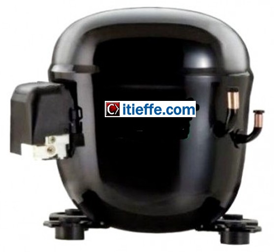
Hermetic: the actual compressor (piston, cylinder, valves, etc.) and the electric motor are enclosed in a single welded casing; the casing is only crossed by the intake and exhaust ducts and the electric power supply cables. It does not need any maintenance, if a single component breaks it is necessary to replace the entire compressor. These compressors are used in small commercial refrigeration, domestic refrigerators and freezers, dehumidifiers, small air conditioners and chillers (water chillers).
Semi-Hermetic: as for the hermetic compressor and electric motor, they are enclosed in a single casing but this can be opened for maintenance operations. In larger units, lubrication is carried out by means of a pump keyed onto the shaft. These compressors are used for medium capacity, commercial refrigeration, air conditioners and medium size chillers.
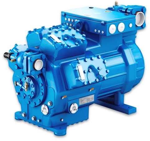
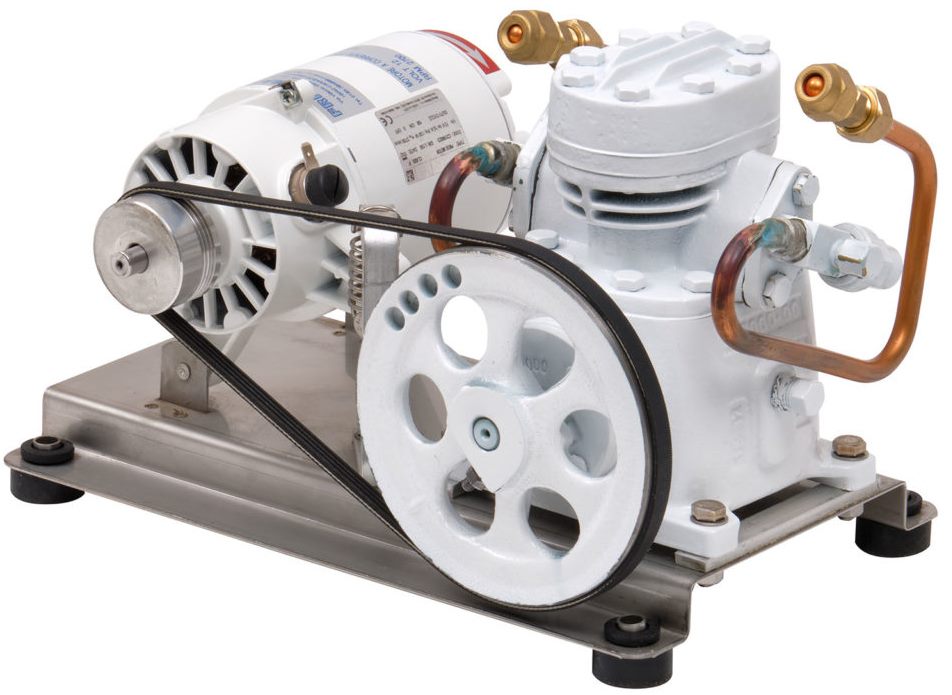
open: the compressor and the engine are two completely distinct entities (it is also possible to find internal combustion engines instead of electric ones). A transmission shaft comes out of the compressor unit to which the motor can be connected by means of a pulley, belts or other. Both the motor and the compressor unit can be fully inspected. These compressors are used for medium and large cooling capacities.
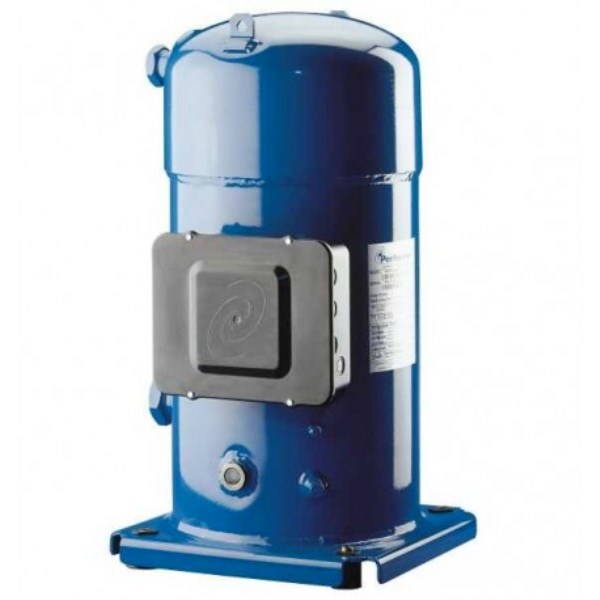
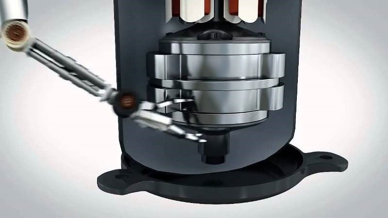
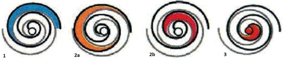
Rotary Scroll Compressors
In Scroll compressors, also called "orbiting spiral", the gas compression occurs thanks to the combined action of two involute spirals coupled together. The first spiral remains fixed while the second performs an orbital movement (not a rotation), thanks to this configuration, gas pockets are created between the coils that move inwards, shrinking and compressing. The compression obtained is extremely uniform, thus avoiding the classic “pulsations” characteristic of reciprocating compressors.
Suction - The gases are sucked into the two large diametrically opposite external pockets.
Compression - The pockets first close progressively and then slide towards the center of the spirals, reducing their volume and compressing the gas.
I unload - When the bags reach the center of the spiral, the gas has reached the delivery pressure and is discharged to the outside through a central port obtained in the fixed spiral.
Twin Rotary Compressors
The most common problems related to rotary scroll compressors concern the correct lubrication at the start with the risk of seizure, the presence of large quantities of oil in the circuit with relative frequent recovery cycles and finally the loss of efficiency at partial loads due to capacity limitation at low frequencies. To solve these problems, a new Twin Rotary compressor was designed, in which there are two vanes.
Thanks to their counter-phase rotation, the opposing centrifugal forces working on the rotation shaft guarantee greater stability at low revs. The "Double Rotor" allows for greater uniformity of rotation during compression operations and a reduction in friction compared to classic rotary machines. The vanes are completely immersed in the oil, significantly reducing the noise produced and the vibrations transmitted to the refrigeration circuit, always maintaining excellent lubrication. Not having a depressive phase to recall the lubricant, the quantity of oil which is introduced into the refrigeration circuit is much lower than with the Scroll compressor.
In particular:
1 = suction
2 = compression
3 = drain
ELECTRICAL PARTS COMPRESSORS
The conformations of the electrical parts of the refrigeration compressors adapted to each individual need according to the various types of connection diagrams of the electrical supplies are described by accessing the link below. The various electrical components necessary for starting and running the compressor are described and are essentially: relays, thermal protectors (clicson), electrolytic capacitors, etc.
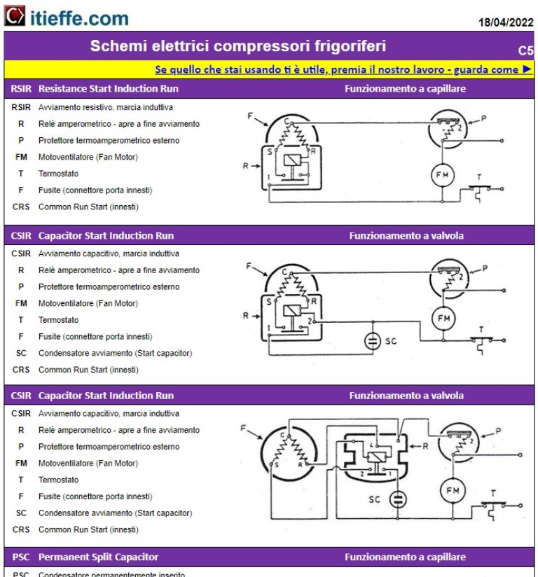
See: "Compressor electrical parts diagrams"
THE HEAT EXCHANGERS
Heat exchangers (in this case condensers and evaporators) are devices that allow the exchange of heat between two fluids at different temperatures. In heat exchangers the two fluids do not mix with each other: the heat is exchanged by convection in both fluids and by conduction through the separating medium between them.
The condenser
The condenser in the refrigerant circuit performs the function of dissipating the heat absorbed by the refrigerant through a fluid which can be water or air. Due to the compression given by the compressor, the fluid reaches the condenser in superheated vapor conditions where it cools and condenses, transferring its heat to the cooling fluid, after which it leaves the condenser in liquid conditions.
Refrigerant enters the condenser in an overheated condition. After a short stretch, the refrigerant reaches saturation conditions and from here begins the stretch affected by the phase change, which usually occupies a large part of the exchanger. Even if in phase change there is a drop in temperature due to the pressure drop suffered by the refrigerant. Once fully condensed, the liquid refrigerant is subcooled until it exits the condenser. The heat transfer fluid which absorbs the heat of condensation is usually single-phase and therefore its temperature increases along the way inside the exchanger. The classification of the condensers is generally done on the basis of the heat transfer fluid used:
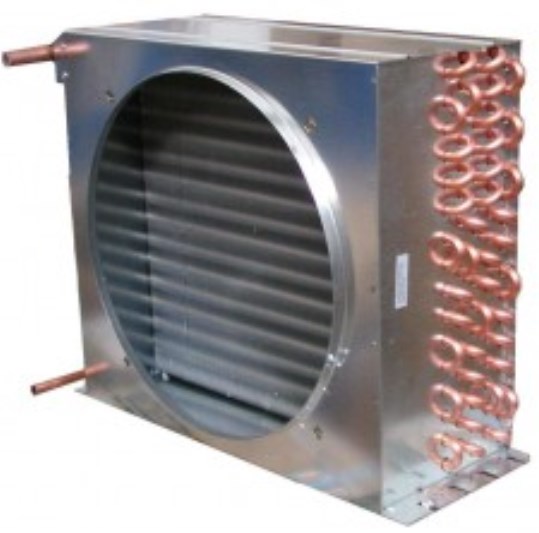
air cooled
water cooled
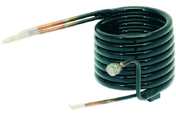
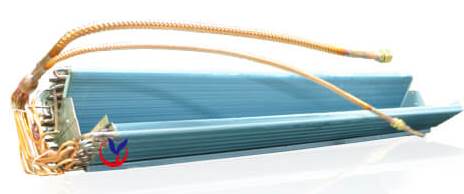
The evaporator
The evaporator performs the function of removing unwanted heat from the fluid to be treated (air or water) to transfer it to the circuit. The refrigerant enters the evaporator with a titer of about 10%, due to the pressure drop during the phase change the refrigerant decreases its temperature even if it absorbs heat until it reaches dry saturated vapor conditions. The refrigerant is superheated until it exits the evaporator, to be sucked in again by the compressor. There are ventilated evaporators that increase their effectiveness by means of a fan and static evaporators that do not resort to this device. Static evaporators offer several advantages in refrigerated cells used for foodstuffs as they remove less humidity from the environment than ventilated ones.
refrigerated cabinet evaporator
split evaporator (independent air conditioner)
THERMAL FLUID
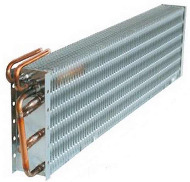
The heat transfer fluid that releases the evaporation heat is usually single-phase (normally air or water) and therefore its temperature decreases along the way inside the exchanger. In the case of air, sometimes pushed by a fan, it touches the evaporator tubes, giving heat to the refrigerant (latent heat of evaporation), making it evaporate. As the refrigerant evaporates, it absorbs heat from its surroundings. The air is cooled and then sent back into the room. To facilitate the evaporation of the refrigerant, copper pipes with a high coefficient of thermal conductivity are used. The copper pipes are inserted in a series of thin fins that increase the surface of the area in contact with the air.
THE REFRIGERANTS
Refrigerant fluids are the means by which heat transfer takes place in the various parts of the refrigeration circuit. The first refrigerant used in vapor compression refrigeration machines was ethyl ether, chosen and used around the middle of the last century by Perkins and Harrison due to its flammability and toxicity and due to the scarce reliability of the sealing systems over time, its use was abandoned. In the second half of the 800th century, other refrigerants were introduced, such as carbon dioxide, ammonia and methyl chloride; the use of these refrigerants undoubtedly contributed to the development of vapor compression refrigeration machines.
However, the safety problem, due to the toxicity and flammability of almost all the refrigerants listed, remained until synthetic refrigerants such as R30, R11, R113, R21, etc. were introduced in the 22s. obtained from methane and ethane by total or partial replacement of the hydrogen atoms with those of chlorine, fluorine and sometimes bromine. Thanks to their excellent thermophysical characteristics and their stability and safety requirements, chlorofluorocarbons (CFCs) established themselves as the predominant refrigerants to replace those previously used, among which practically only ammonia (R717) remained for industrial applications.
But the environmental problem, in terms of ozone destruction and global warming due to the greenhouse effect, has partly de-legitimized the role played by the so-called CFCs in the last fifty years; hence the need to replace CFCs with other fluids, which has prompted the technical world to envisage and examine the various possibilities, but at the same time posed the problem of "Retro fi t", that is, the conversion of all existing systems and their adaptation to new refrigerants.
The new refrigerants
Starting from the late 70s, the chemical industry began to work to identify new substances suitable for use in refrigeration systems, replacing CFCs and later also HCFCs that were creating many environmental problems such as decrease in stratospheric ozone. The substances that have been identified, and which belong to the class of HFC hydrofluorocarbons, have been evaluated both from a toxicological point of view (International PAFT Consortium) and from an environmental point of view (AFEAS International Consortium). The new refrigerants are characterized by a high chemical stability, which makes them suitable for use in almost all operating conditions that can be encountered in refrigeration and air conditioning systems. These new fluids are mixtures of various compounds and depending on their behavior they are defined:
- Azeotropes: they are mixtures that do not change either their volumetric composition or their temperature of saturation during evaporation (absence of glide effect); therefore, changes of state occur a constant pressure and temperature.
- Almost Azeotropes: they present a slight variation in temperature during the transition of state (small glide effect) which however does not compromise the performance and operation of the system.
- Zeotropes: they have a marked "glide" effect, that is, the passage of states occurs at constant pressure but not at constant temperatures. When designing the machinery, this particularity must be taken into account if you intend to use a zeotropic fluid. This mixture being formed by a more volatile and a less volatile part, in the event of leaks, the lighter component will easily leak. In this way, only the heavier component will remain in the circuit, often with poor cooling characteristics. Therefore, in the event of a fault, the system must first be completely emptied and the mixture “recreated” by replenishing the lost component and finally, after having repaired the leak, the circuit must be refilled.
The main HFC refrigerants:
- R134A
- R407C
- R410A
For more details, please refer to the following links:
Refrigerant temperature pressure ratio
Typical applications
Typical refrigerant gas applications with indication of the type of fluid, R number, which product it replaces, composition and manufacturer.
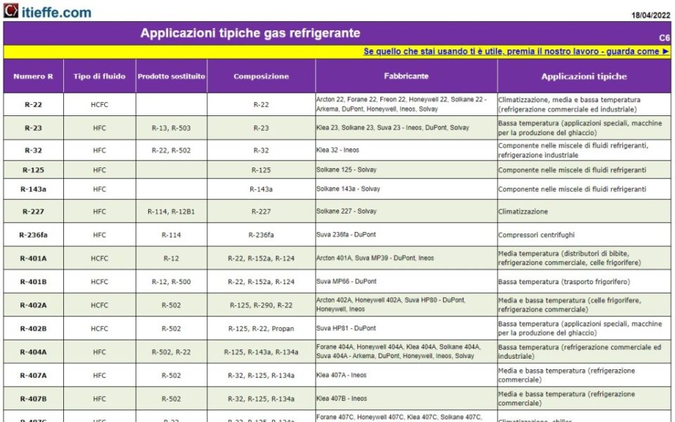
See full version "Typical refrigerant gas applications"
THE LAMINATING ORGAN
From a purely thermodynamic point of view, the lamination member serves to lower the pressure and the temperature between the two heat exchangers of the reverse vapor compression cycle. In practice, its main function is to regulate the flow of refrigerant from the condenser to the evaporator so that it is always commensurate with the refrigeration capacity that the system must guarantee. The classification between the different rolling elements is based on the ability to adapt their geometry to the different load conditions (variation of the required cooling capacity).
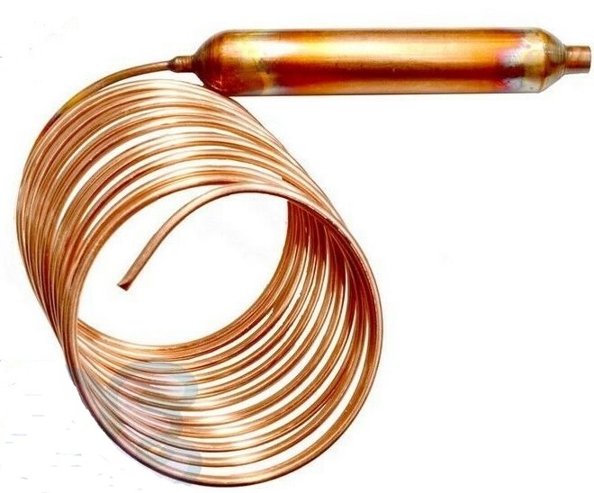
The capillary tube
It is the most common lamination organ in small and very small refrigeration machines and air conditioners. Liquid refrigerant is forced to pass through this extremely narrow tube. The energy lost in passing through the capillary brings the refrigerant from a high pressure state to a very low pressure state. in these cases operating conditions different from the nominal ones are spontaneously established with a decrease in efficiency.
The thermostatic expansion valve
Thermostatic expansion valves control the injection of liquid refrigerant into the evaporators and protect the compressor motor from liquid refrigerant.
The thermostatic expansion valve allows to keep the superheat (or the refrigerant level) constant in situations of variable load in the refrigeration system, in order to save energy.
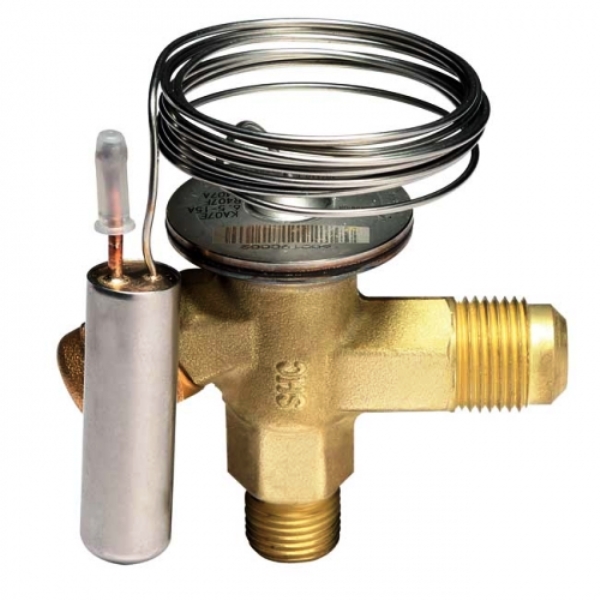
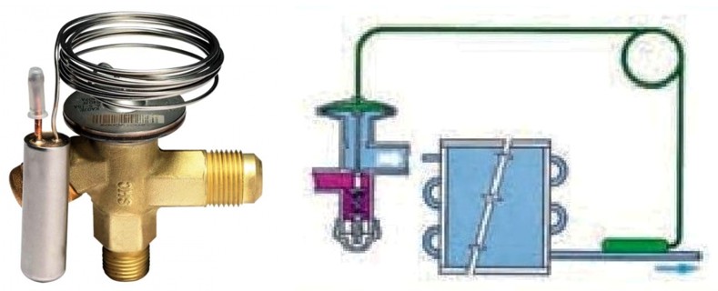
Thermostatic valve and insertion on the evaporator
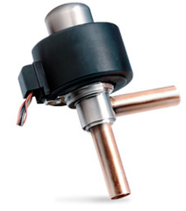
The electronic lamination valve
It acts like a thermostatic valve except that it is not self-activated by means of the pressure system created in the valve. It is a true electronically operated electronic control system.
Rolling elements that adapt their geometry to the load:
- thermostatic expansion valve
- electronic expansion valve
Rolling elements that do NOT adapt their geometry to the load:
- capillary tube
- constant pressure valve
MAIN ACCESSORIES
Oil separator
It is positioned downstream of the compressor: the oil collects in the lower part of the separator and is reintroduced into the crankcase by means of an automatic drain.
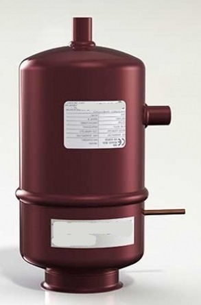
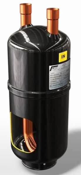
Liquid separator
It allows to separate the liquid part from the vapor part; in this way you can be sure that you are only fishing from the top of steam.
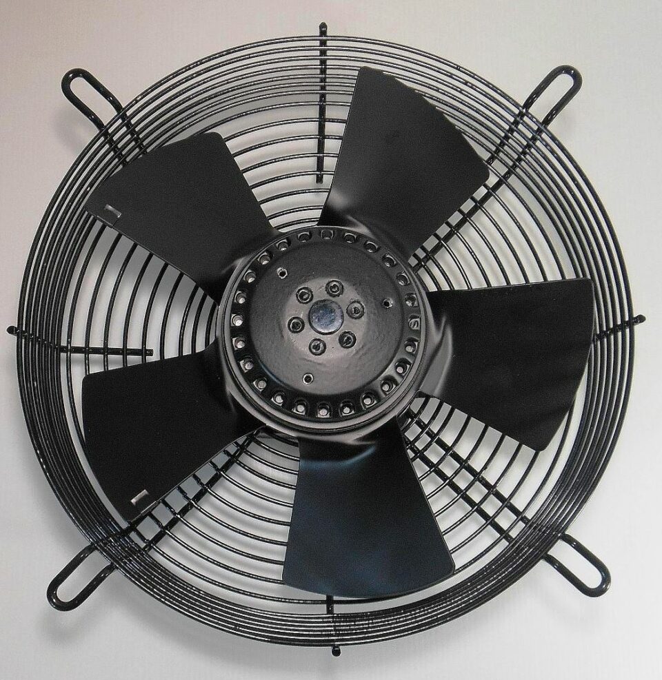
Condensing fan
To increase the dissipation of heat in the condenser, a fan called condensation is applied. This arrangement allows a greater passage of air in the unit of time through the condenser, considerably increasing the condensing power of the apparatus.
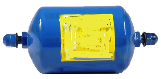
Filter drier
To remove moisture from the circuit and small debris, a filter called a dehydrator is inserted in the line. Together with it, in the case of a circuit with valve (no capillary) a liquid passage indicator is added (also called "Specula")
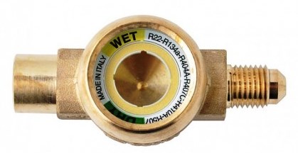
Liquid sight glass
liquid passage indicator (also called "Specula") also acts as a humidity indicator (color change of the ring placed in the sight glass)
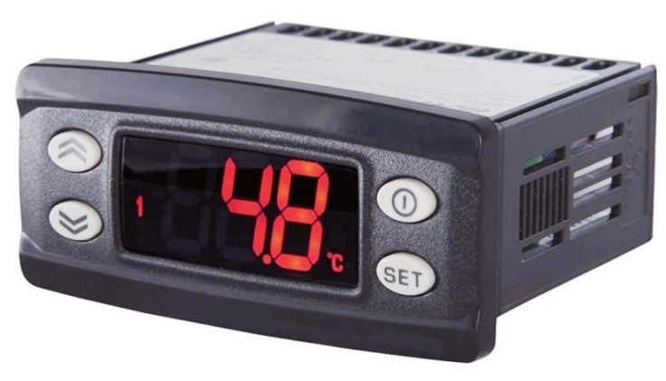
Thermostat
To set the temperature of the apparatus used, the thermostat is used, which is nothing more than a switch controlled by the temperature.
Other types of thermostat
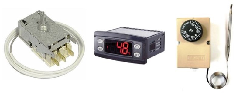
Antiquity (evergreen)