
General information on what high spots are in water heating and refrigeration circuits, how to examine them and eliminate them.
Welcome to the guide created by Itieffe "High points of water circuits (air in the water circuits of thermal plants)". In a world where water and air meet in an intricate ballet within thermal systems, this guide will take you on a fascinating journey into the complex relationship between these two vital elements.
Thermal systems, whether they are intended for heating, cooling or energy production, often involve the interaction between water and air. This synergy can have a significant impact on efficiency. In this guide, we will explore how air plays a crucial role in the water circuits of thermal systems and how its management affects the overall results.
Through a journey that ranges from the basics of thermodynamics to advanced engineering, we will guide you through the dynamics that characterize the interaction between air and water. We will explore how air can affect blistering, corrosion and thermal efficiency within heating systems. Through case studies, practical advice and technical insights, you will have the opportunity to gain an in-depth understanding of how air can be optimally managed to maximize plant benefits.
This guide is not only aimed at those working in thermal engineering, but also at anyone interested in discovering the marriage between water and air that gives life to many of the technologies that surround us. You will learn how small details, such as air purging, can have a major impact on the efficiency and life of your heating systems.
We invite you to join us on this journey through the fluid harmony of the water circuits of thermal plants, where water and air intertwine in a complex but fundamental dance. Let this guide be your road map in exploring the challenges and opportunities offered by the interaction between air and water, guiding you towards a deeper understanding and more effective management of thermal systems.
Notes on the high points of the water heating and cooling circuits
In all hydraulic circuits for water heating and cooling, the presence of air bubbles causes an inevitable malfunction of the system.
The presence of air prevents the normal circulation of the carrier fluid and consequently the blocking of the system.
Just think of the single radiator: if there is air at the height of the manual bleed valve, it stops working. To get it back to its job, you have to remove the air.
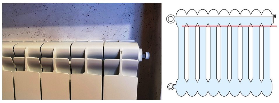
When the water does not exceed the red stripe, the radiator freezes.
Removing the air, the red line reaches the black and the radiator begins to work regularly.
It should be noted that every time the air is removed, the pressure of the circuit is lowered, consequently if it is a closed vessel circuit, it must be restored using the filling tap.
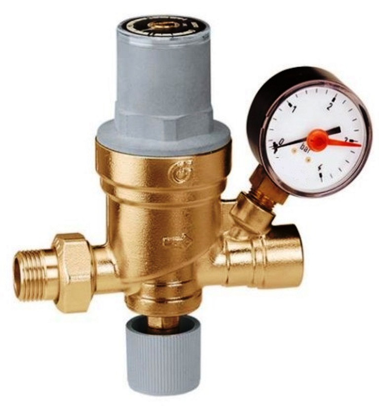
If there is an automatic filling unit (obviously calibrated), this operation is not necessary
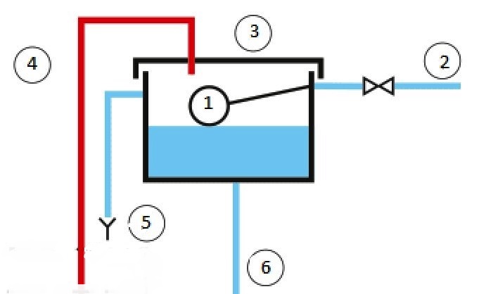
If the circuit is open vessel, nothing needs to be done: the float takes care of it
1 float
2 water fill (make-up)
3 expansion vessel
4 safety tube
5 too full
6 water filling in the circuit
All pipes that reach a higher level than the others must have air purges (automatic or manual).
It means that if a line goes up, then goes down and then goes up again, at all high points, there must be some way to purge the air.
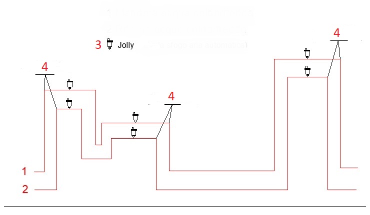
1 Hot / cold water delivery
2 Hot / cold water return
3 Jolly - automatic air vent valve
4 high points
The air bubbles that form in the high points block the circulation of water even in the presence of a circulation pump.
The creation of air purges is therefore mandatory.
Pay attention that in the case of an automatic bleed valve (jolly) near the intake of the circulation pump with a high head, there may be air pockets, in which case it is more suitable to insert manual air bleeds.
Keep in mind that manual air purges must be carried out with the circulation pump off and with the water temperature equal to the ambient one.
Let's take some examples
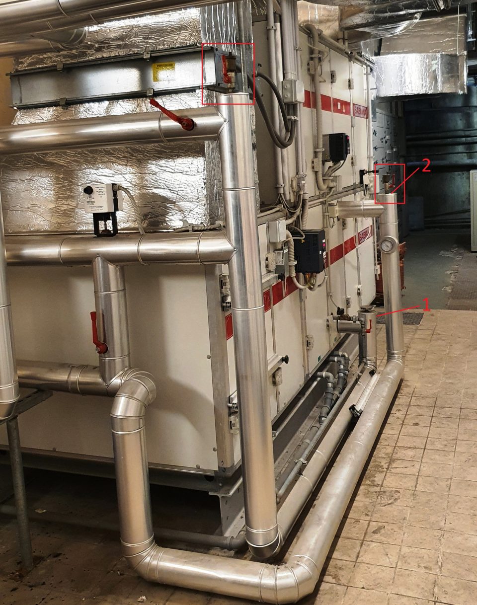
In point 1 manual air vents have been correctly inserted.
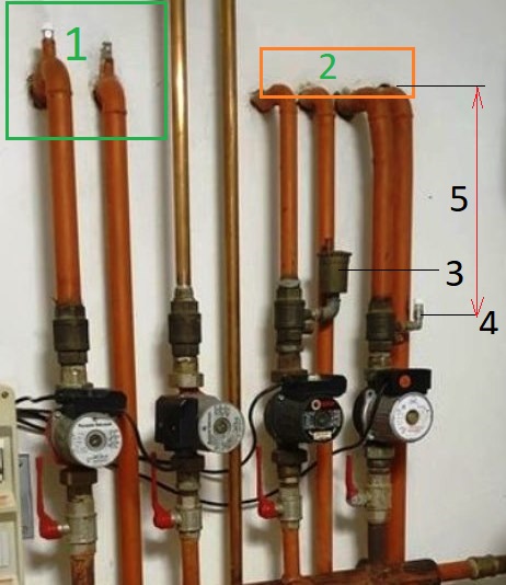
In points 3 and 4 of the figure, they have respectively inserted a joker and a manual air vent valve that are not needed absolutely to remove air from the circuit above them leaving the piping line labeled with the 5 always full of air.
To avoid this, air vents must be inserted in zone 2 (one for each high point).
Let's take another example
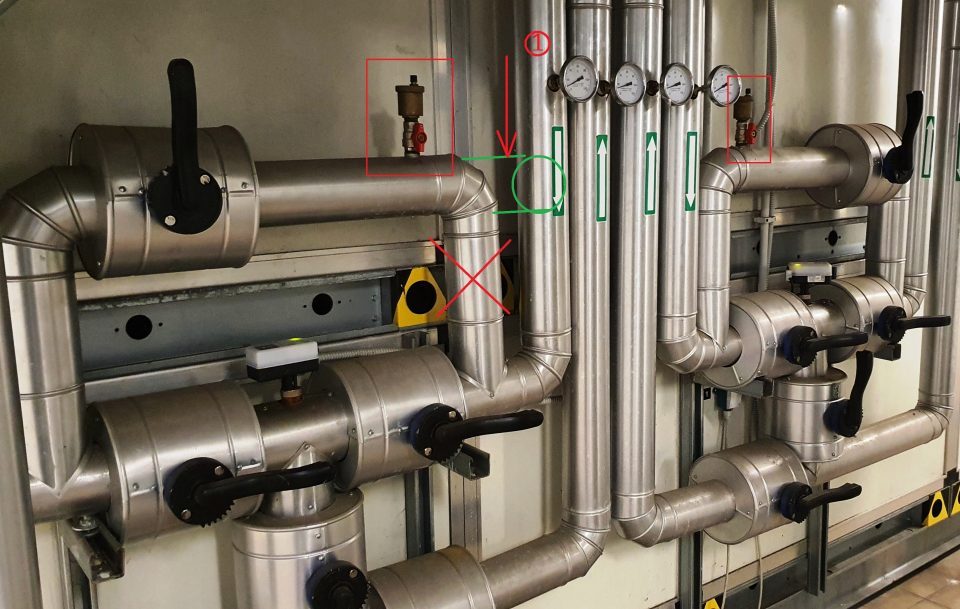
The Bypass of this circuit formed a high point where it was necessary to insert a Jolly.
If the fitter had carried out the distribution of the fluid as indicated by point 1 (the pipe marked with X would not have existed), the Jolly would have had no reason to exist as it would have to be present at the top of the pipe. (1).
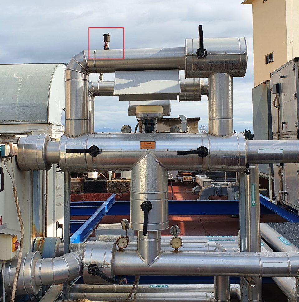
Other examples of correct installation of the Jokers in the high points of the circuits
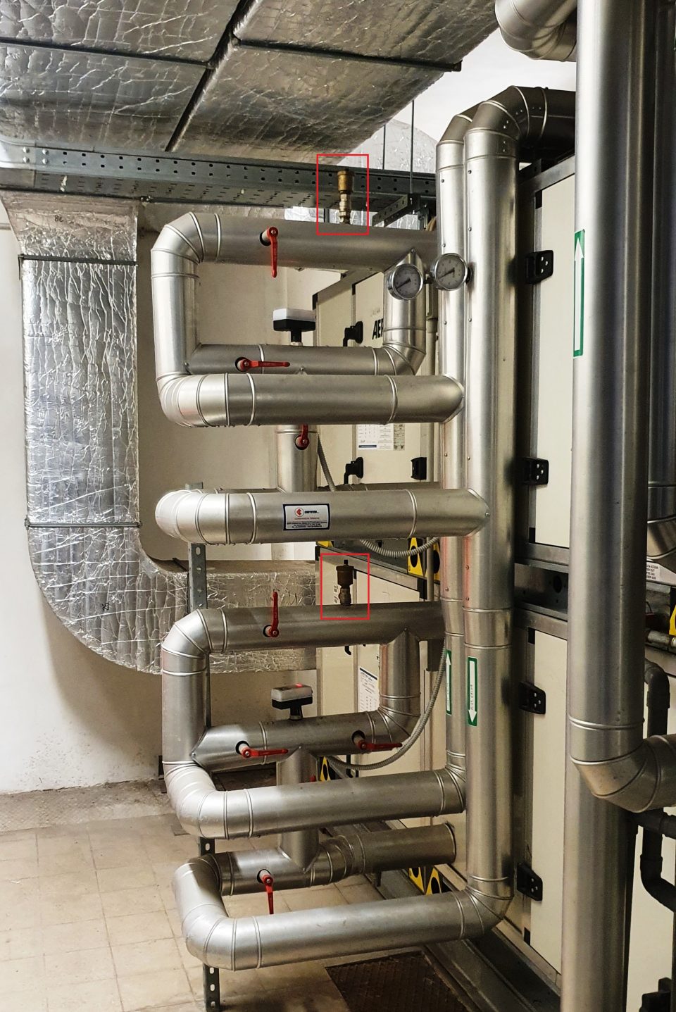
The vertical pipe is equipped with automatic purge valves in the opposite part of the photo (not visible) as this is where the high point exists.
In the last drawing, at point 1 no air vent should be put in as there is a Jolly at the highest point of the coil (2).
Common provisions
Another thing that can be noticed in many installations of water distribution manifolds, both hot and cold, is the lack of air vents in the high points that obviously are created.
Many installers believe that the water circulation pump is sufficient to remove the air bubbles that are created and perhaps in some cases it happens. But why risk it?
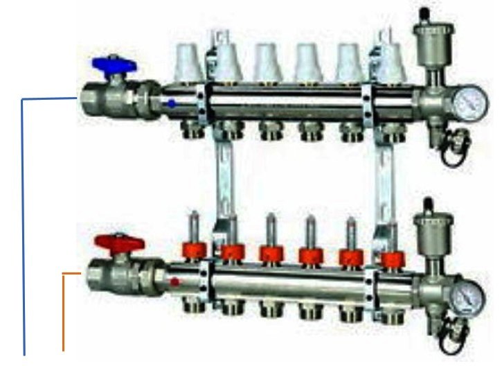
Drawing 1 shows the correct installation of the Jokers at the head of the supply lines, coming from below.
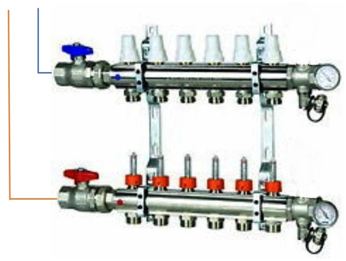
In the case of drawing 2, with the supply lines coming from the top, the Jokers must not be mounted as the high points are sent back above the manifold.
Extended implant
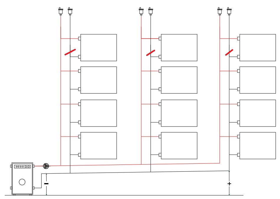
In drawing 3 a column system is shown: as you can see, it is not necessary to insert manual air vent valves on the radiators as all the air that is formed, starting from the boiler room, is conveyed to the high points where there are Jokers that provide for its elimination. It should be noted that in many cases, the Jokers inserted on the return pipe are not necessary and can be omitted.
How to properly bleed the air from individual radiators (or end users).
We try to illustrate the correct way to remove the air from radiators / radiators / fan coils and other final appliances.
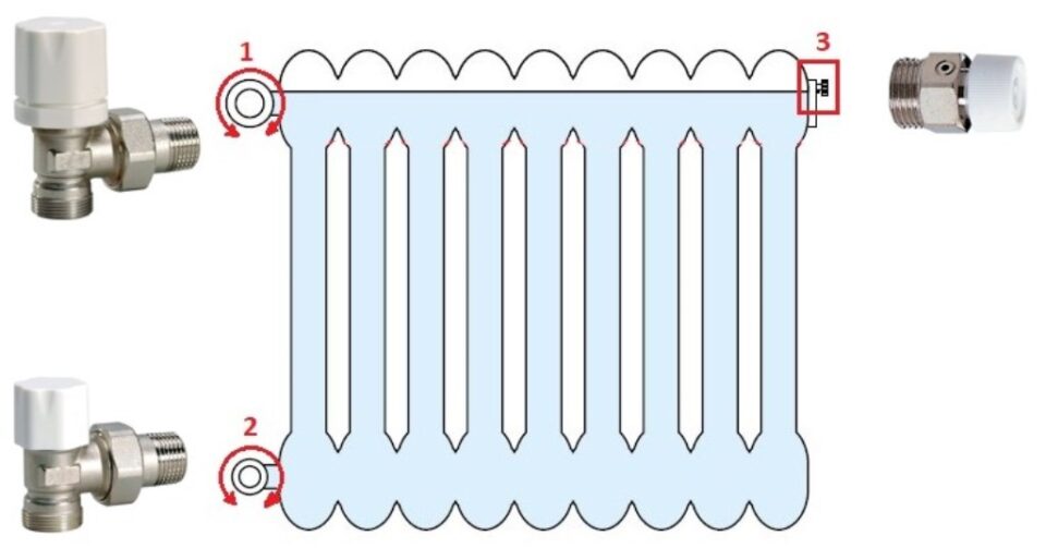
1 - radiator valve
2 - radiator holder
3 - manual vent valve (small valve)
How to proceed:
this is a job that must be done with the system water at room temperature and the circulation pump stopped;
- valve and holder must be completely open;
- close valve 1 well (clockwise rotation) leaving lockshield 2 open;
- slowly open the air purge valve 3 and keep it open until air comes out. If a lot of air comes out, close the valve every now and then and check the filling pressure which must never drop below 0,5 bar, if necessary, top up the water (this is not necessary in the event of an open expansion tank or active filling unit) . When only water comes out, close the valve 3 and the holder 2;
- open valve 1 (anticlockwise rotation);
- slowly open the air purge valve 3 and keep it open until air comes out. If a lot of air comes out, close the valve every now and then and check the filling pressure which must never drop below 0,5 bar, if necessary, top up the water (this is not necessary in the event of an open expansion tank or active filling unit) . When only water comes out, close the valve 3;
- open the lockshield 2 using the special tool (screwdriver, Allen wrench, etc.).
At this point all the air present inside the radiator has been completely evacuated and if the problem was only due to this, it should be solved.
Conclusion
Follow the circuit with an attentive eye, find all the high points and reason: “but where does the air come from above this point”.
If you don't find it, that's a high point.
Adjust accordingly.
Other free programs of the same kind offered by itieffe ▼
- Heating - Plumbing
- Pipelines
- Heating tables
- pumps
- Heating drawing diagrams
- Domestic hot water
- Combustible gases